Porsche PDK 7DT45 — Standalone Wiring
Running a 7DT45 from the standalone controller means the factory control unit is not used and the controller drives the mechatronics directly.
This is not the same as the OEM PDK gateway. The gateway keeps the factory control unit and talks to it. This page is the standalone route, where the controller drives the transmission itself. See PDK configuration if you meant the gateway.
Read DCT standalone drivers first — it covers the control strategy, its inputs and outputs, its parameters and its maps. This page is only the wiring.
Follows cross table version 1.1. Version 1.1 added the control valves for the active differential, so a loom built to an earlier table will be missing them.
Two harness variants — one is a subset of the other
Two variants exist, and the earlier one is a strict subset of the later one. Not a different arrangement: the same connections, minus four.
| 20-way connector | |
|---|---|
| Earlier | pins 1–16 |
| Later | pins 1–20 |
The later variant adds exactly four connections, all at the top of the 20-way connector — pins 17, 18, 19 and 20. Everything else is identical, pin for pin, on both. The 16-way connector is the same on both.
So one loom covers both. Build to the later variant. On an earlier transmission those four wires simply have nothing to land on — nothing needs rerouting and no pin means something different.
The connectors
Five, and it is worth being clear which side each is on before reading the table:
| Connector | Side | Ways | |
|---|---|---|---|
| PDK-A | Transmission | 16 | |
| PDK-B | Transmission | 20 | |
| DT06-12 | Loom | 12 | This is the signal converter — see below |
| DTM06-12 | Loom | 12 | |
| DT04-4P | Loom | 4 |
The DT06-12 is easy to mistake for a plain inline joint, because the cross tables list it beside the other two Deutsch connectors and number its ways the same way. It is not a joint. A module sits behind it, and six of the channels on this transmission pass through that module rather than round it.
The signal converter
Six channels do not run straight from the transmission to the controller. A module sits in the loom behind the DT06-12, and there are two different arrangements around it. Both are shown here before the pin table, because the pin table on its own reads like six direct wires.
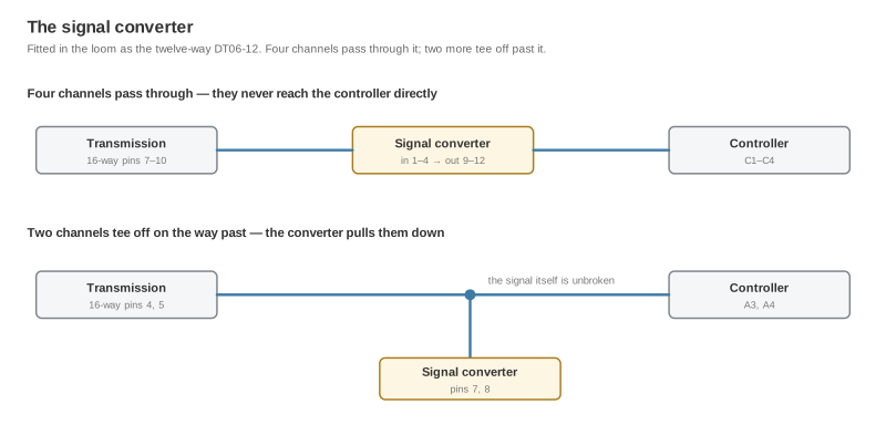
Four channels pass through it — C1 to C4
PDK-A 7, 8, 9, 10 land on converter pins 1, 2, 3, 4. They leave on converter pins 9, 10, 11, 12, and only those outgoing wires reach the controller, at C1–C4.
⚠️ There is no wire from PDK-A to the controller for any of these four. A wire run straight from PDK-A 7 to C1 bypasses the module. The channel will still read something, which is why this one is easy to leave in a loom.
Two channels tee off past it — A3 and A4
PDK-A 4 and 5 run unbroken to A3 and A4. Partway along each, a second wire branches to converter pins 7 and 8, where the module pulls the line down.
The signal wire itself is not cut here. The converter pin is a second connection off the same line — the same shape as the pull-up below, pulling the other way.
Converter pinout
| Converter pin | Connects to | What it is |
|---|---|---|
| 1 | PDK-A 7 | In |
| 2 | PDK-A 8 | In |
| 3 | PDK-A 9 | In |
| 4 | PDK-A 10 | In |
| 5 | M1 — sensor supply | Module supply |
| 6 | L2 — sensor ground | Module ground |
| 7 | Branch off the A3 line | Pull-down |
| 8 | Branch off the A4 line | Pull-down |
| 9 | C1 | Out |
| 10 | C2 | Out |
| 11 | C3 | Out |
| 12 | C4 | Out |
The module is powered from the same M1 and L2 that feed the transmission's own supply pins, so it needs nothing beyond the two pins already in the table below.
Controller pin to connector
Every controller pin the configuration uses, and where each lands. A blank means that pin does not appear on that connector.
Six rows say more than a pin number. Where the converter column reads in … out …, the PDK-A wire ends at the module and a different wire carries on to the controller. Read the cell, not just the number.
| Controller pin | PDK-A (16) | PDK-B (20) | Signal converter (DT06-12) | DTM06-12 | DT04-4P |
|---|---|---|---|---|---|
| M1 — sensor supply | 3, 12 | 13 | 5 — module supply | 5 | |
| L2 — sensor ground | 13 | 14 | 6 — module ground | 6 | |
| M3/M4 — battery positive | 1, 15, 16, 17 | 1, 2 | |||
| L1 — switched ignition | 3 | ||||
| L3/L4 — chassis ground | 4 | ||||
| A1 | 7 | ||||
| A2 | 8 | ||||
| A3 | 4 — direct to A3 | 7 — pull-down tap off that wire | |||
| A4 | 5 — direct to A4 | 8 — pull-down tap off that wire | |||
| B3 | 9 | ||||
| B4 | 10 | ||||
| C1 | 7 — stops at the converter | in 1, out 9 → C1 | |||
| C2 | 8 — stops at the converter | in 2, out 10 → C2 | |||
| C3 | 9 — stops at the converter | in 3, out 11 → C3 | |||
| C4 | 10 — stops at the converter | in 4, out 12 → C4 | |||
| D1 | 13 ⚠ | ||||
| D3 | 11 | ||||
| D4 | 12 | ||||
| E1 | 10 | ||||
| E2 | 18 | ||||
| E3 | 4 | ||||
| E4 | 3 | ||||
| G1 | 1 | ||||
| G2 | 2 | ||||
| G3 | 12 | ||||
| G4 | 11 | ||||
| H1 | 2 | ||||
| H2 | 3 | ||||
| H3 | 4 | ||||
| H4 | 5 | ||||
| J1 | 6 | ||||
| J2 | 7 | ||||
| J3 | 8 | ||||
| J4 | 9 | ||||
| K1 | 20 | ||||
| K2 | 19 |
Three places the sources disagree
Three cross tables cover this transmission and they do not fully agree. Two of the three disagreements now have a majority; one does not. Confirm all three against your own loom before crimping.
| Position | Status |
|---|---|
| PDK-B 13 | Two sources say sensor supply (M1). Cross table 1.1 also assigns D1 here, which cannot be right — the same pin cannot be both. Treat as M1. |
| PDK-B 19 and 20 ⚠ | Two sources put K1 on 19 and K2 on 20; cross table 1.1 has them the other way round. The majority is against 1.1 here. This is the expensive one to get wrong — it crosses two power outputs, so two valves are driven by the wrong channel. |
| PDK-B 18 | Unresolved. Every source agrees which transmission channel this is; they disagree on whether it lands on D1 or E2. |
All three sit on the four pins the later variant adds. On an earlier transmission none of them exists, so none of this applies — the disagreements only matter if you are wiring a later unit.
The table above still shows cross table 1.1 as published. It has not been silently corrected — the discrepancies are recorded here instead so the decision stays with you.
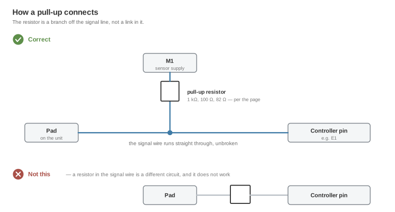
The pull-up
E1 needs a 2.2 kΩ pull-up. The wire runs to E1 unbroken; the resistor is a second connection from that same line to the sensor supply, M1.
Shielding
A3 and A4 run in shielded cable, with the shield to ground. They are the two channels that suffer if the switched outputs are routed alongside them, and they are the ones this table calls out specifically.
Keep the output loom and the signal loom apart wherever the routing allows — shielding is not a substitute for separation.
Wire gauge and terminals
Two of the source tables specify gauges, and they do not match. They appear to describe different parts of the loom, but that is not stated anywhere, so both are given here rather than one being picked.
From the controller cross table
0.35 mm² throughout unless listed:
| Run | Gauge |
|---|---|
| M3/M4 battery positive, L3/L4 chassis ground | 1 mm² |
| H1–H4, J1–J4 | 0.75 mm² |
| Everything else | 0.35 mm² |
From the connector cross table
This one also gives the terminals, and its cross-sections are larger than the factory harness on most circuits — the original runs 0.35 mm² on much of this, and that is not the target.
| Circuit group | Cross-section | Terminal part number |
|---|---|---|
| Supply rails | 1.5 mm² | 968075-3 |
| Grounds | 0.7 mm² | 968074-2 |
| Switched output channels | 0.7 mm² | 5-963715-1 |
| Sensor supplies and signal channels | 0.5 mm² | 5-963715-1 |
Cross-reference: the OEM grey connector
For splicing into the factory harness rather than fitting the loom connectors. This maps the two transmission-side connectors onto the OEM grey connector's own pin numbers.
| PDK-A pin | Grey pin | PDK-B pin | Grey pin | |
|---|---|---|---|---|
| 3 | 18 | 1 | 2 | |
| 4 | 27 | 2 | 35 | |
| 5 | 28 | 3 | 36 | |
| 7 | 21 | 4 | 37 | |
| 8 | 32 | 5 | 38 | |
| 9 | 34 | 6 | 39 | |
| 10 | 33 | 7 | 40 | |
| 12 | 19 | 8 | 15 | |
| 13 | 4 | 9 | 14 | |
| 10 | 13 | |||
| 11 | 30 | |||
| 12 | 31 | |||
| 13 | 20 | |||
| 14 | 3 | |||
| 15 | 23 | |||
| 16 | 25 | |||
| 17 | 24 | |||
| 18 | 41 | |||
| 19 | 6 | |||
| 20 | 16 |
Note that the grey pins here are the transmission-side ends. On the four channels that pass through the signal converter, splicing at the grey connector puts you on the input side of the module, not on the wire that reaches the controller.
Controller-side connections
⚠️ M3/M4 needs a time-delay-off supply, not a plain main relay. The controller writes its state after the ignition drops. A relay that opens with the ignition cuts the supply mid-write and corrupts the adaptations this driver learns. Hold it for about 60 seconds: advisory.
Before first power-up
- Resolve the three conflicts above. They are not safe to guess at.
- Give M3/M4 a time-delay-off supply — see the advisory.
- Check the pull-up on E1 while you can still reach it.
- Confirm the signal converter is in circuit. C1–C4 should read open to PDK-A with the module unplugged. If they read through, the four channels have been wired straight past it.
- Confirm every channel in the datalogger before letting the driver command anything. A channel that reads plausibly but wrong is the failure mode these pages keep warning about.
Related documentation
- Device pinout — the controller connector and its supply requirements
- DCT standalone drivers
- PDK gateway configuration — the other approach
- Supported PDK variants
- Stated limitations