The Configuration workspace
Applies to: IOcan · Standalone controller. What this means
This is where a configuration starts. The left half selects what the device is talking to; the right half assigns its pins. Nothing else can be set until the left half is complete.
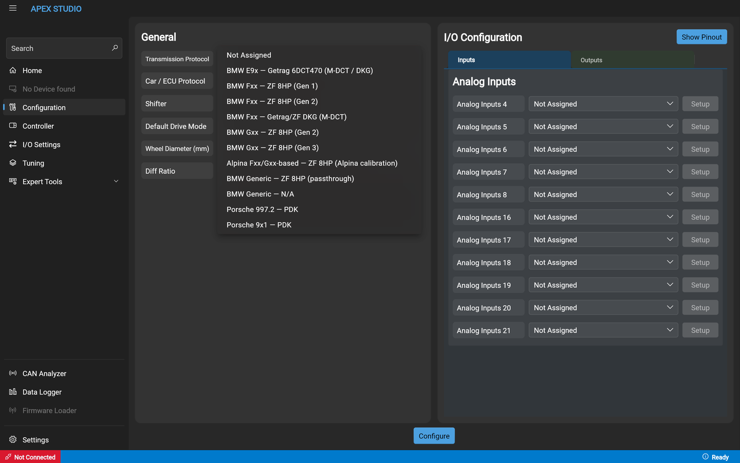
The lists in the screenshots are examples of the layout, not a compatibility list. For what is actually supported, read Supported vehicles & modules, which is maintained against the firmware.
Starting one
From Home, choose Create New for a blank configuration or Open Config to load one from a file. Creating a new one asks which device you are configuring before anything else.
The General section
Three selections drive everything downstream — transmission, ECU and shifter — plus the vehicle figures the controller needs.
The panel has rows for Transmission Protocol, Car / ECU Protocol, Shifter, Default Drive Mode, Wheel Diameter and Diff Ratio. The I/O configuration sits alongside it on the right, with Inputs and Outputs tabs and a Show Pinout button, and a Configure button runs along the bottom.
Each of the ECU and shifter rows carries its own CAN channel selector. They do not have to share a bus. The transmission protocol has no channel selector of its own.
Transmission protocol
Car / ECU protocol
The list is long and filterable — type into the box at the top rather than scrolling. It mixes OEM engine ECUs with aftermarket ECUs.
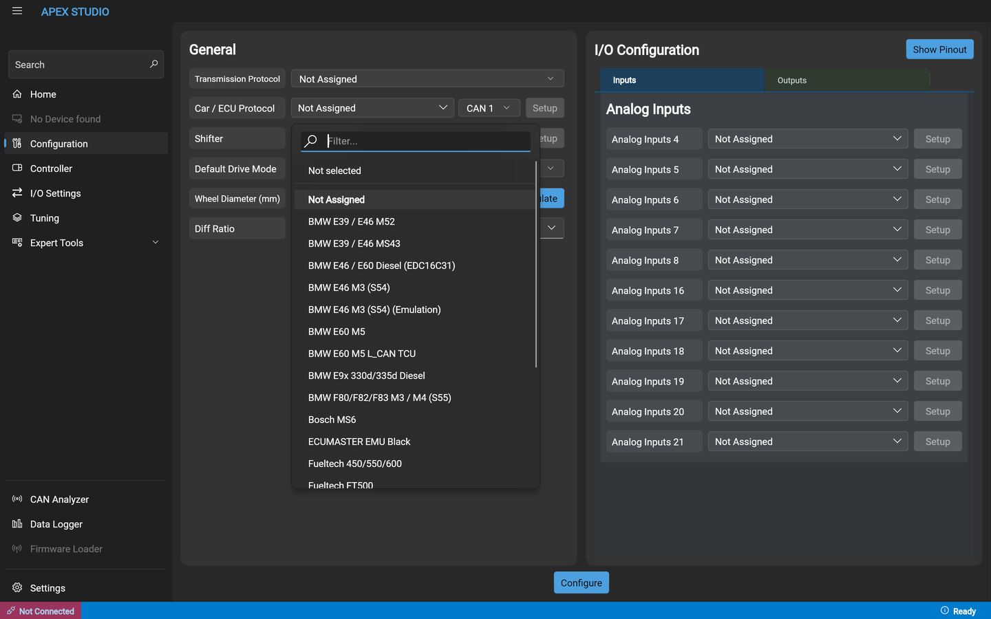
The aftermarket entries each have a setup page here: Aftermarket ECU integration.
Shifter
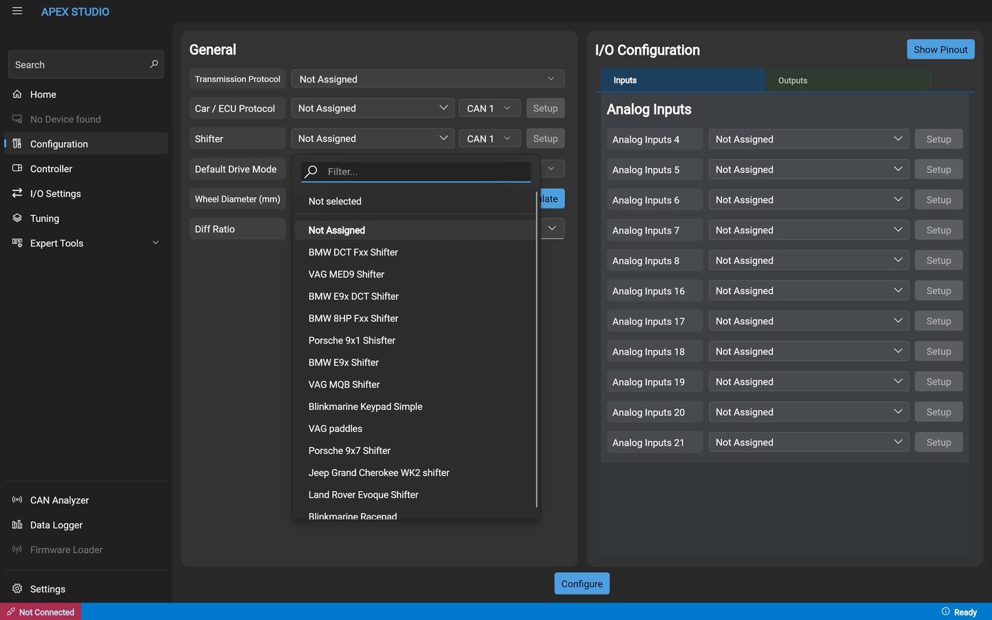
How each of these is wired and what it needs is on Shifter integration.
Per-protocol setup
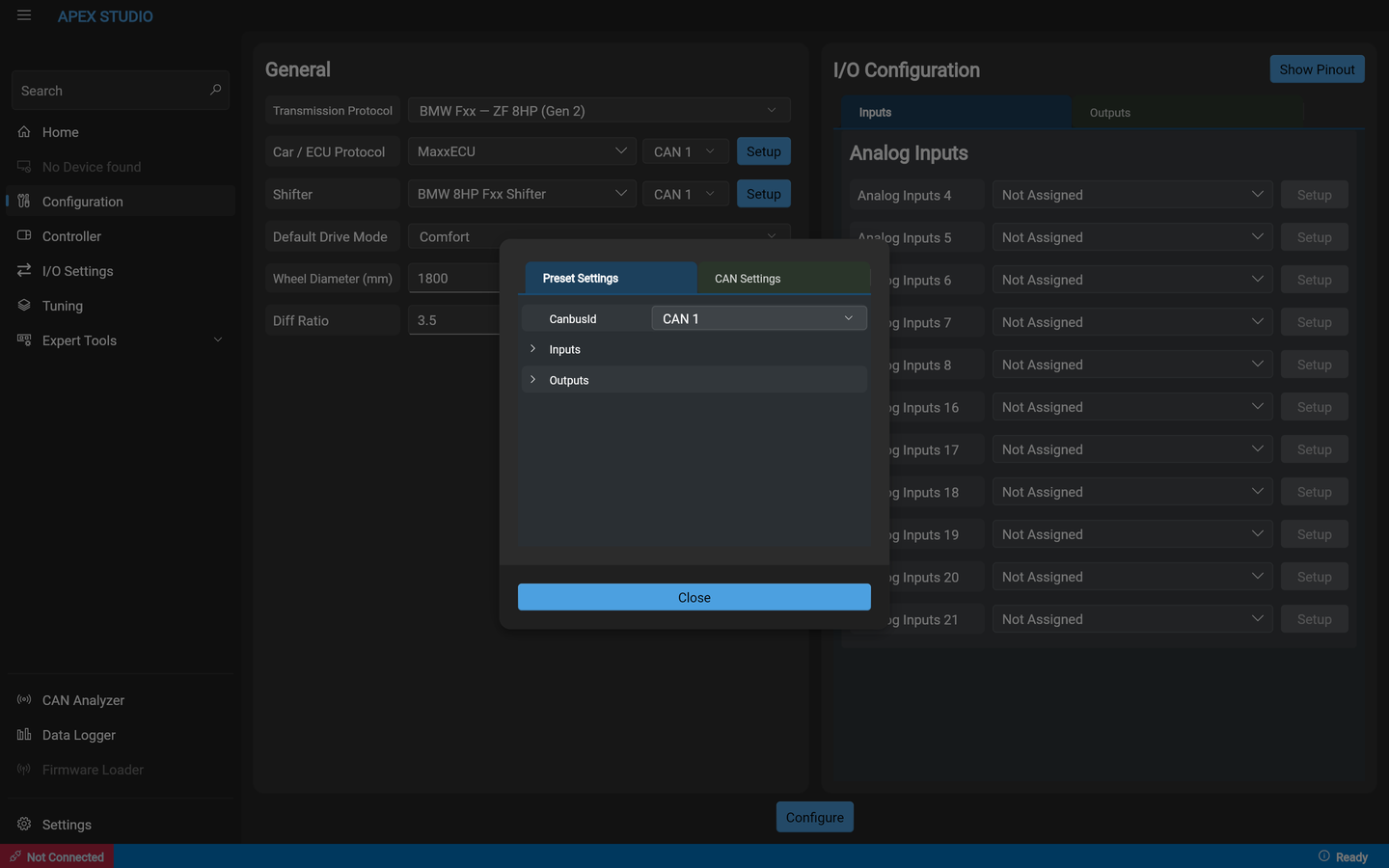
The Setup button beside a protocol opens its own settings — a Preset Settings tab for what the preset itself exposes, and a CAN Settings tab for the bus it runs on. Inside Preset Settings, the preset's own inputs and outputs are collapsible groups.
The I/O configuration
The right-hand panel assigns the device's pins. Each row is one pin, with a dropdown for what it becomes and a Setup button for that assignment's own parameters.
What the types do is documented per type: all input types · all output types.
The pinout viewer
Show Pinout draws the physical connector with every pin coloured by what it is currently assigned to, and lists what each pin is capable of alongside.
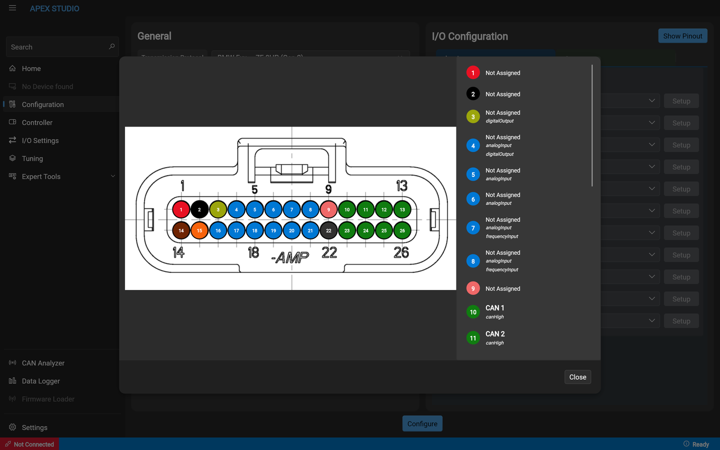
This is the fastest way to answer "can this pin do that?" — the capability list under each pin is the same constraint the configuration enforces, so a type that is not listed there cannot be assigned to that pin.
The same information in table form is on IOcan's pinout and the standalone controller's pinout.