DQ500 — 26-pin Connector Cross Table
The loom-side allocation for the 26-pin round connector on a DQ500 standalone build: which controller pin each connector pin lands on, and which transmission-side circuit feeds it.
One external loom for three gearboxes
The outside wiring is deliberately common across the dual-clutch builds. The connector pin to controller pin map below is identical on DQ500 gen 1, DQ500 gen 2 and the DKG — all 26 pins. That is by design, not coincidence: the allocation was chosen so the external loom does not change with the gearbox.
What that buys you:
- One patch loom part. The run from the connector to the controller is the same whichever of the three you are building, so it can be made, stocked and reused without rework.
- A gearbox swap does not touch the outside. Change the transmission and the internal loom changes with it; everything from the connector out stays put.
- One thing to check when a channel misbehaves. If the outside loom is correct for one build it is correct for all of them, which narrows a fault to the inside wiring or the mechatronic work.
⚠️ This deliberately does not extend to the DQ250. It uses the same 26-pin connector and mates perfectly, but ten pins land on different controller pins — by design, not by accident. See the DQ250 page. Label your looms.
Only the transmission side differs, which is why the table gives a circuit column per generation. The connector, its pin arrangement and its wire cross-sections are on the DKG wiring cross table.
Controller pin designations (H1, C1, …) refer to the
device pinout. The mechatronic work is on
DQ500 gen 1 and DQ500 gen 2.
Cross table
Inside is the run from the mechatronic unit to the connector; outside is the run from the connector to the controller.
| Pin | Gen 1 circuit | Gen 2 circuit | Controller pin | Inside length |
|---|---|---|---|---|
| 1 | SV2 | S2 | H1 | 35 cm |
| 2 | A3 | A15 | C1 | 32 cm |
| 3 | B3 | B1 | C2 | 39 cm |
| 4 | SV13 | S13 | K2 | 35 cm |
| 5 | SV3 | S3 | H2 | 35 cm |
| 6 | C3 | A5 | C3 | 20 cm |
| 7 | D3 | A9 | C4 | 10 cm |
| 8 | — | — | D1 — 4.7 kΩ pull-up | — |
| 9 | SV11 | S11 | K1 | 35 cm |
| 10 | SV4 | S4 | H3 | 35 cm |
| 11 | — | — | D2 — 4.7 kΩ pull-up | — |
| 12 | E3 | A1 | A3 | 18 cm |
| 13 | F3 | F2 | A4 | 12 cm |
| 14 | PS_A | A7 | D3 | 10 cm |
| 15 | SV10 | S10 | J4 | 35 cm |
| 16 | SV5 | S5 | H4 | 35 cm |
| 17 | PS_B | A4 | D4 | 10 cm |
| 18 | G2 | A13 | B3 | 19 cm |
| 19 | G4 | A11 | E1 — 2.2 kΩ pull-up | 20 cm |
| 20 | SV9 | S9 | J3 | 35 cm |
| 21 | SV6 | S6 | J1 | 35 cm |
| 22 | Sensor ground | Sensor ground | L2 | 10 cm |
| 23 | Sensor 5 V supply | Sensor 5 V supply | M1 | 10 cm |
| 24 | SV7 | S7 | J2 | 35 cm |
| 25 | SV1 / SV8 / SV12 | S1 / S8 / S12 | Battery positive | 35 cm |
| 26 | SV1 / SV8 / SV12 | S1 / S8 / S12 | Battery positive | 35 cm |
Pins 25 and 26 are both battery positive. The three solenoid supply positions are commoned onto two connector pins rather than one, so the supply current is shared across two terminals. Wire both.
Pins 8 and 11 carry nothing on a DQ500 — and that is the shared allocation working as intended. They land on D1 and D2 with a 4.7 kΩ pull-up each, which the DKG uses for its mechatronic terminals MC6 and MC8. On either DQ500 generation no transmission circuit reaches them, so there is nothing to connect on the inside. Leave them in the external loom rather than deleting them: that is what keeps the loom interchangeable.
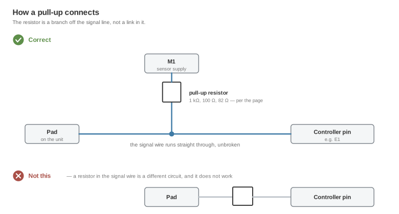
Pin 19 is used on all three, and its pull-up matters. The topology is the same tee as every other pull-up on these pages, never in series:
Reading the gen 1 circuit column
The gen 1 designators map onto the pad groups on
the gen 1 page: a letter is the group and the
number is the pad within it, so A3 is group A pad 3. PS_A and PS_B are the
two sensors under the stock control unit cover, and SVn are the solenoid
connector positions.
Reading the gen 2 circuit column
The gen 2 designators are the mechatronic main connector terminals — A1–A17,
B1, F2 — and Sn are the solenoid positions. See
the gen 2 page.
Related documentation
- DQ500 gen 1 wiring · DQ500 gen 2 wiring
- DKG wiring cross table — the same connector
- Device pinout
- DCT standalone drivers