Audi DL501 — Standalone Wiring
Running a DL501 from the standalone controller means the OEM control unit comes out and the controller drives the mechatronics directly.
⚠️ This modification is not reversible. The control unit's bond wires are destroyed getting to the pads. A mechatronic unit prepared this way cannot be returned to standard. Be sure of the plan before starting.
The DL501 is heavy. Get help or a crane before you plan to lift it onto a bench. This is not a gearbox to wrestle with alone.
Read DCT standalone drivers first — it covers the control strategy, its inputs and outputs, its parameters and its maps. This page is only the wiring.
What you need
- Soldering station
- Dremel with an abrasive disc — you will need it, see cleaning the pads
- Torx drivers
- Side cutters
- Tweezers
- 24 AWG (0.2 mm²) silicone or PTFE wire — oil resistant, rated to 200 °C
This work needs soldering experience and a steady hand. The joints are in very tight locations and there is no room to be casual about them.
Stripping it down
- Drain the fluid by removing the screw in the oil pan.
- Unscrew the pan cover once the fluid is mostly out. Expect some still inside — it does not all come out of the drain.
- Unscrew the oil filter base.
- Unscrew the Torx holding the round case connector, then twist the connector to release it.
- Remove the plastic cover and disconnect the pin from the mechatronic unit.
- Remove the mechatronic unit from the transmission body — six screws.
- Degrease the whole assembly once it is out and you have found the plate covering the control unit. It makes everything after this easier and keeps the bench clean.
- Depin the two connectors on the side of the plate.
- Remove three screws to separate the transmission control unit from the rest.
- Remove the screws holding the cover down to reveal the control plate.
Removing the bond wires
The stock controller connects to the pads around it with fine aluminium wire. Remove all of it with tweezers, holding each wire as close to its pad as possible so little or none is left behind.
Cleaning the pads
This is the step that catches people out. The pads are covered in a protective gel, and solvents will not touch it — degreaser, nitro thinner and acetone all fail.
- Remove the gel mechanically. Tweezers and cotton buds are the practical combination.
- The bottom connectors need more than that. They carry a coating that prevents soldering, and it has to come off with a Dremel-type tool and an abrasive disc before solder will wet the pad.
Do not skip ahead to soldering because a pad looks clean. A joint made onto gel or coating will pass a visual check and fail later, sealed inside a gearbox.
Soldering
- Measure the wire lengths before cutting. Too short is the failure that shows up months later — leave enough that nothing is under tension.
- Tin the wire tips before soldering them to the pads.
- Check for shorts to the thin traces between pads after every joint. The traces run close and the gaps are small.
Pad groups
The control plate carries six pad groups. A, B, D and E are multi-way strips; PSA and PSB are the two three-pad round groups at the bottom of the plate.
⚠️ Pad letters and controller pin letters are not the same thing. Pad A6 goes to controller pin B3; pad D2 goes to controller pin A3. Both systems use A–E and they do not line up. Read the column, not the letter.
Group A — 14 pads
| Pad | Controller pin |
|---|---|
| A1 | Not connected |
| A2 | Not connected |
| A3 | E3 — plus a 1 kΩ resistor from this line to M1 |
| A4 | L2 — sensor ground |
| A5 | M1 — sensor supply |
| A6 | B3 — plus a 100 Ω resistor from this line to M1 |
| A7 | H1 |
| A8 | BAT+ |
| A9 | see note |
| A10 | H2 |
| A11 | H3 |
| A12 | BAT+ |
| A13 | see note |
| A14 | H4 |
Group B — 14 pads
| Pad | Controller pin |
|---|---|
| B1 | J1 |
| B2 | BAT+ |
| B3 | see note |
| B4 | J2 |
| B5 | J3 |
| B6 | BAT+ |
| B7 | see note |
| B8 | J4 |
| B9 | K1 |
| B10 | BAT+ |
| B11 | see note |
| B12 | K2 |
| B13 | Not used |
| B14 | Not used |
Five pads are unconfirmed. A9, A13, B3, B7 and B11 are blank in the source. Do not guess at them — ask before soldering those five.
Group D — 9 pads
| Pad | Controller pin |
|---|---|
| D1 | Not connected |
| D2 | A3 — plus a 100 Ω resistor from this line to M1 |
| D3 | A4 — plus a 100 Ω resistor from this line to M1 |
| D4 | Not connected |
| D5 | L2 — sensor ground |
| D6–D9 | Not connected |
⚠️ Group D needs confirming before you solder it. The connection sheet assigns D2 and D3 to the frequency inputs, but the control-plate photograph marks group D with a cross as unused. Those two cannot both be right, and getting it wrong means the two speed channels land on the wrong connector. Confirm which strip is D on your unit before committing.
Group E — 12 pads
| Pad | Controller pin |
|---|---|
| E1 | C1 |
| E2 | C2 |
| E3 | C3 |
| E4 | L2 — sensor ground |
| E5 | M1 — sensor supply |
| E6 | C4 |
| E7 | M1 — sensor supply |
| E8 | L2 — sensor ground |
| E9 | D1 |
| E10 | D2 |
| E11 | D3 |
| E12 | D4 |
PSA and PSB — 3 pads each
The two round groups at the bottom of the plate. Both wire identically apart from their signal pin.
| Pad | PSA | PSB |
|---|---|---|
| 1 | M1 — sensor supply | M1 — sensor supply |
| 2 | E1 | E2 |
| 3 | L2 — sensor ground | L2 — sensor ground |
The pull-ups
Four resistors. A pull-up is not in the signal wire — each line runs to its controller pin unbroken, and the resistor is a second connection from that same line to the sensor supply, M1:
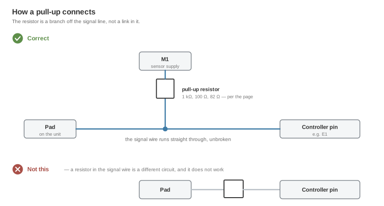
| Pad | Runs to | Resistor from that line to M1 |
|---|---|---|
| A3 | E3 | 1 kΩ |
| A6 | B3 | 100 Ω |
| D2 | A3 | 100 Ω |
| D3 | A4 | 100 Ω |
Fit them at the controller end of the loom, where they stay reachable. A missing pull-up shows up as a channel that reads plausibly wrong rather than as a dead channel, which is the harder fault to find.
Wire gauge
| Run | Gauge |
|---|---|
| Power outputs and BAT+ | 1 mm² |
| Frequency inputs | Screened core — see below |
| Analog inputs, sensor ground, sensor supply | 0.25 mm² |
Use screened cable for the three frequency inputs. They run alongside ten switched outputs, and they are the channels that suffer for it. Keep the solenoid loom and the signal loom separate as well — the screen is not a substitute for routing.
Controller-side connections
| Controller pin | Connect to |
|---|---|
| M3 and M4 | Battery positive — both pins |
| L1 | Switched ignition |
| L3 and L4 | Engine or chassis ground — both pins |
⚠️ M3/M4 needs a time-delay-off supply, not a plain main relay. The controller writes its state after the ignition drops. A relay that opens with the ignition cuts the supply mid-write and corrupts the adaptations this driver learns. Hold it for about 60 seconds: advisory.
Closing up
- Check every joint before sealing, then protect the soldered points with silicone packing so nothing can short.
- Seal the pads and the wires so they cannot move. Movement is what eventually breaks a joint, and transmission fluid finds anything left open.
- Keep the solenoid loom away from the signal loom. Do not braid them together.
Related documentation
- Device pinout — the controller connector and its supply requirements
- DCT standalone drivers
- DQ500 gen 1 · DQ500 gen 2 · DQ250 — the same job on the other VAG units
- Stated limitations