CAN Gateway Pinout
Connector: 1473712-1 (TE Connectivity Superseal 1.0mm 26pos, 2 row version)
Terminals:
- 1-1437284-0 (16 - 14 AWG / 1.25-2mm²)
- 1437284-9 (18-16 AWG / 0.75-1.25mm²)
- 3-1447221-3 (16-18 AWG)
- 3-1447221-4 (20 AWG)
- 3-1447221-5 (22 AWG)
| Pin Name | Pin | Pin | Pin Name |
|---|---|---|---|
| KL30 IN | 1 | 14 | KL31 |
| KL30B OUT | 2 | 15 | KL15IN |
| PWR6/WAKEUP OUT | 3 | 16 | AN1/PWR1 |
| AN2/PWR2 | 4 | 17 | AN3/PWR3 |
| AN4/PWR4 | 5 | 18 | AN5/PWR5 |
| AN6 | 6 | 19 | AN7 |
| AN8/FREQ2 | 7 | 20 | AN9/FREQ1 |
| AN10/FREQ4 | 8 | 21 | AN11/FREQ3 |
| SENSOR5V | 9 | 22 | sGND |
| CAN1H | 10 | 23 | CAN1L |
| CAN2H | 11 | 24 | CAN2L |
| CAN3H | 12 | 25 | CAN3L |
| CAN4H | 13 | 26 | CAN4L |
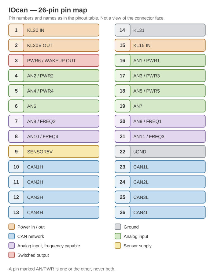
The same 26 pins grouped by what they do. It follows the table above — it is not a view of the connector face, so do not use it to identify a physical cavity.
Pin description
Terminal names starting with KL are names according to DIN 72552
KL31
KL31 - return to battery- or chassis ground. This pin should be connected with wire of at least 1.5mm²
KL30 IN
KL30 - constant battery+ This device is optimized for low power consumption in standby - 0.5mA - it is strongly recommended to keep this terminal on constant bat+ or delayed off. This pin should be wired with at least 1.5mm²
KL30B OUT
KL30B - delayed off battery+. This pin is intended to power the transmission and is capable of supplying 15A.
KL15IN
KL15 - Battery + through ignition switch. This pin should be connected with wire of 0.35mm2
ANx - x between 1 and 7
ANx - Analog input capable of measuring voltages of up to 16V
ANx - x between 8 and 11
ANx - Analog input capable of measuring voltages of up to 6V
PWRy - y between 1 and 6
PWRy - Low current power output, rated 0.9 A per channel. All six share a pin with something else, so a pin is one or the other and never both:
- PWR1 to PWR5 share pins 16, 4, 17, 5 and 18 with analog inputs AN1 to AN5. These are the five general-purpose outputs listed in the technical specifications.
- PWR6 shares pin 3 with WAKEUP OUT, the transmission wake-up signal. That is its normal job, but it is not reserved — on an installation that does not use transmission wake-up, PWR6 can be configured as a general-purpose output like the other five.
Assigning two outputs to the same pin raises fault 0x0014; assigning an
output to a pin with no power stage raises 0x0081. Both are listed in
Fault codes.
FREQz - z between 1 and 4
FREQz - Inputs for speed signals
sGND
sGND - this pin supplies ground, for all sensors connected to analog and frequency inputs.
SENSOR5V
SENSOR5V - this pin supplies 5V to sensors connected to analog and frequency inputs.
CANxL and CANxH - x between 1 and 4
This pin pairs are used to connect gateway to different CANbus networks. This device has configuration-switchable 120Ohm termination.