BMW DKG (GS7D36SG) — Standalone Wiring
This modification is irreversible. Once the bond wires have been pulled and the stock control unit is out of the mechatronics, the unit can never again run under its factory TCU — and without a working factory TCU the transmission can no longer be used behind the IOcan gateway either. If you want to keep the OEM TCU and the option of returning to stock, the IOcan route is the reversible alternative.
Driving the Getrag GS7D36SG — BMW's 7-speed dual-clutch transmission — from a standalone controller means modifying the mechatronics unit inside the transmission: the factory control unit comes out, and the solenoid valves and sensors are cabled straight out of the case.
This page is organised in two layers. Transmission-side modification covers all work on the transmission itself and is written without reference to any particular controller — the wires it produces are identified purely by signal and by label. Controller connections then assigns those wires to controller pins. The companion wiring cross table gathers the complete set of connections and wire specifications in one place.
What follows is one straightforward, low-risk way of carrying out the conversion. Any other method is just as valid, provided the finished point-to-point connections come out identical.
Transmission-side modification
Nothing in this section depends on which standalone controller will eventually run the transmission.
Required tools and materials
- Soldering station
- Dremel-type tool with abrasive disc
- Torx set (T25, T10)
- Side cutters
- Tweezers
- 1 mm² and 0.35 mm² wire — silicone or PTFE insulated, oil resistant, 200 °C rated
- 0.2 mm² (24 AWG) wire for the solder-pad links
- Silicone sealant (e.g. Victor Reinz Reinzosil)
Caution: the solder joints sit in very cramped locations. Take this job on only if you have soldering experience and a steady hand.
Recommendation: fit a noise-suppression circuit to reduce the chance of interference reaching the sensor inputs.
Disassembly
Undo the T25 Torx bolts around the DCT mechatronics cover and lift the cover away — expect some residual transmission fluid to escape as you do.
- Free the main connector from the mechatronics unit: lift its plastic lock upwards, then draw the connector out.
- Undo the round connector in the gearbox housing. Removing it entirely
means reaching in with a long tool to unlatch and disconnect the plug on
the temperature and input shaft speed sensor that sits behind the
clutches. Taking the front clutch dust cover off first makes the plug far
easier to reach:
- Take off the front clutch dust cover.
- The Torx screw retaining the ground clip is clearly visible from the front of the transmission. Remove it without letting it drop.
- Slip a long screwdriver in at the side-pan opening where the loom turns towards the case connector — from the front you can see it well.
- Press gently down on the connector from the top while drawing the leads out.
- Take the control unit off by removing every bolt circled in the diagram below. With the unit out, degreasing the whole assembly is strongly advised — the remaining work becomes cleaner and easier, and an ordinary universal degreaser or brake cleaner does the job.
- Gently lever the plastic covers off the solenoid connectors.
- Undo the T10 Torx bolts holding the aluminium cover of the electronic control unit, then lift the rubber seal out carefully so it comes through the rest of the work undamaged.
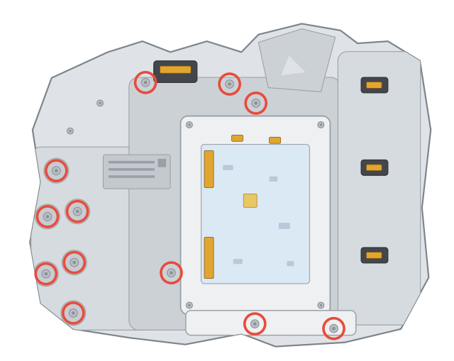
Control unit hold-down bolts (step 3), viewed from the controller side — every circled position must come out.
Rear sensor (temperature and input shaft speed)
Pull the original wires out of the sensor's 4-pin connector and fit new ones in their place. The replacement leads carry these signals:
| Sensor pin | Signal |
|---|---|
| 1 | input shaft speed |
| 2 | sensor ground |
| 3 | transmission temperature |
| 4 | not used |
The sensor can also stay on its connector, at the cost of having to identify its wires at the original main connector (MC) and label them before cutting. Mark the wires that run to original MC pins 4, 5 and 6:
| OEM MC pin | Sensor pin | Signal |
|---|---|---|
| 4 | 3 | transmission temperature |
| 5 | 2 | sensor ground |
| 6 | 1 | input shaft speed |
Removing the stock controller
Study the pad naming and numbering before touching anything — the transmission will only work if every wire later lands on its correct pad.
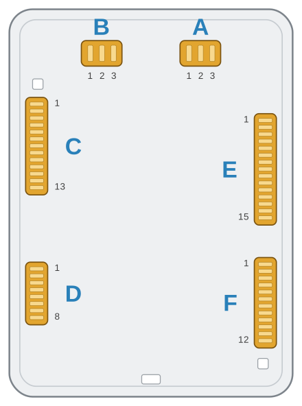
Solder pad groups with the stock controller removed — A and B along the top, C and D on the left, E and F on the right. Pad 1 of each side connector is the topmost pad.
Thin aluminium bond wires tie the stock controller to the pads that surround it. Pull them all out with tweezers, gripping each one as close to its soldering pad as possible so that next to nothing — ideally nothing at all — is left behind.
The pads then have to be cleaned mechanically: the protective gel coat does not yield to degreaser, nitro thinner or acetone. Lifting it off with tweezers and cotton buds works best. Pad groups A and B carry an extra coating that stops solder from taking; grind it off with a Dremel-type tool and abrasive disc.
Solder pad cross connections
Work out how long each 0.2 mm² (24 AWG) link wire needs to be, and err on the generous side — a wire under tension is a connection waiting to fail. Tin the wire ends before soldering them to the pads.
Check that nothing shorts against the thin track running between pads C2 and C3.
| Pad | Connect to |
|---|---|
| E1 | A2 |
| E2 | B2 |
| E3 | C2 |
| E4 | C3 |
| E5 | C4 |
| E6 | C6 |
| E7 | C8 |
| E8 | keep unconnected |
| E9 | C10 |
| E10 | C11 |
| E11 | C12 |
| E12 + E13 (merged) | D2, D3, D6, D7, F2, F3, F6, F7, F10, F11 |
| E14 | A1, B1, C5 |
| E15 | A3, B3, C7, C9, C13 |
The E pads work as collection points: E1–E11 each carry a single sensor signal, the merged E12/E13 pair forms the solenoid supply rail, E14 gathers the sensor grounds and E15 the sensor 5 V feeds.
Once everything is soldered, confirm that no two pads are shorted together. Then bed the solder pads and the wires in silicone so nothing can shift and work a joint loose later on.
Refit the rubber seal before the aluminium cover goes back on.
Solenoid wiring
Tin every solder pad on the solenoid connectors (pad groups D and F). Each connector carries one signal pad and one supply (VCC) pad; the supply pads — D2, D3, D6, D7, F2, F3, F6, F7, F10 and F11 — were tied to the merged E12/E13 rail during the solder-pad step and sit at +12 V whenever the ignition is on.
Cut the solenoid leads long enough to terminate comfortably outside the transmission, and label the signal wires 1 to 10. Label them dependably — a mixed-up wire here becomes a mis-wired solenoid later. The signal pad of each solenoid is:
| Solenoid | Signal pad |
|---|---|
| 1 | D1 (A) |
| 2 | D4 (B) |
| 3 | D5 (A) |
| 4 | D8 (B) |
| 5 | F1 (A) |
| 6 | F4 (B) |
| 7 | F5 (A) |
| 8 | F8 (B) |
| 9 | F9 (A) |
| 10 | F12 (B) |
A and B denote the two pads of a solenoid connector — notice how the signal pad alternates from one solenoid to the next.
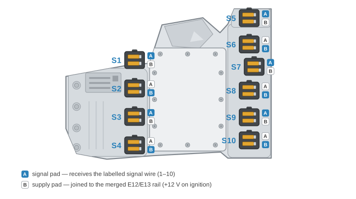
The solenoid side of the mechatronics — S1–S4 on the valve body, S5–S10 along the opposite edge. The highlighted pad of each connector is the signal pad. Pre-made looms use black wire for all ten solenoids, labelled S1–S10.
Main connector (MC) leads
The main connector can be dealt with in either of two ways: tin the existing wire tips and solder extensions onto them — sized so the finished leads match the solenoid wires in length — or crimp entirely new leads using GS7 main-connector terminals, which are available separately. Use 20–18 AWG (0.5–0.8 mm²) wire on terminals MC1–12 and 15–13 AWG (1.5–2.5 mm²) on MC14–16. The terminal numbers are marked on the connector itself; the diagram below confirms the layout.
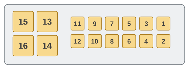
Main connector seen from the back (wire-entry) side — power terminals 13–16 on the left, signal terminals 1–12 on the right.
Routing the loom out of the transmission
Keep the valve loom and the sensor loom apart: solenoid wiring is electrically noisy, and braiding it together with the interference-prone sensor signals invites trouble. Sleeving all wiring in heat shrink inside the case is also worth the effort for the added protection.
The round connector serves purely as a feed-through in the transmission case — drill it open, pass all the wires through, and finish with a silicone seal (e.g. Victor Reinz Reinzosil).
Alternatively the loom can end in a 26-pin bulkhead connector; the pin assignment and wire cross-sections for that variant are documented in the wiring cross table.
Controller connections
The pin assignments below apply to the standalone controller documented on the device pinout page. Any other device needs its own mapping tables in place of these — the transmission-side work above stays exactly the same.
⚠️ Two supply decisions belong in the harness design, not at commissioning.
- BAT+/KL30 needs a time-delay-off relay, holding the supply about 60 seconds after the ignition drops. The controller saves its state after KL15 goes away; cut the supply at the same moment and adaptation data is corrupted. The HELLA 5HE 996 152-131 is a known working part.
- Do not wire KL30 to permanent battery as the alternative. The controller has no low-power sleep mode — with KL30 present it keeps drawing 200–300 mA and will flatten the battery in hours.
Full detail: Adaptation data lost when the supply drops with the ignition.
Rear sensor
| Sensor pin | Controller pin | Notes |
|---|---|---|
| 1 | FREQUENCY IN3 (B3) | |
| 2 | sGND (L2) | |
| 3 | ANALOG IN9 (E1) | add a 2.2 kΩ pull-up to SENSOR_5V (M1) |
| 4 | not used |
Solenoids
Every labelled solenoid wire goes to the output with the matching number:
| Solenoid | Signal pad | Controller pin |
|---|---|---|
| 1 | D1 (A) | PWM OUT1 (H1) |
| 2 | D4 (B) | PWM OUT2 (H2) |
| 3 | D5 (A) | PWM OUT3 (H3) |
| 4 | D8 (B) | PWM OUT4 (H4) |
| 5 | F1 (A) | PWM OUT5 (J1) |
| 6 | F4 (B) | PWM OUT6 (J2) |
| 7 | F5 (A) | PWM OUT7 (J3) |
| 8 | F8 (B) | PWM OUT8 (J4) |
| 9 | F9 (A) | PWM OUT9 (K1) |
| 10 | F12 (B) | PWM OUT10 (K2) |
Main connector
| MC terminal | Controller pin | Notes |
|---|---|---|
| 1 | ANALOG IN1 (C1) | |
| 2 | ANALOG IN2 (C2) | |
| 3 | ANALOG IN3 (C3) | |
| 4 | ANALOG IN4 (C4) | |
| 5 | FREQUENCY IN1 (A3) | |
| 6 | ANALOG IN5 (D1) | add a 4.7 kΩ pull-up to SENSOR_5V (M1) |
| 7 | FREQUENCY IN2 (A4) | |
| 8 | ANALOG IN6 (D2) | add a 4.7 kΩ pull-up to SENSOR_5V (M1) |
| 9 | — | can be removed |
| 10 | ANALOG IN7 (D3) | |
| 11 | ANALOG IN8 (D4) | |
| 12 | — | empty |
| 13 | SENSOR_5V (M1) | |
| 14 | fused (25 A) +12 V supply | joined with BAT+/KL30 (M3, M4) |
| 15 | sGND (L2) | |
| 16 | fused (25 A) +12 V supply | joined with BAT+/KL30 (M3, M4) |
Power supply and grounds
- Battery +12 V, switched by the main relay, feeds BAT+/KL30 (M3, M4).
- Ignition-switched +12 V goes to WAKEUP/KL15 (L1). The controller has internal protection, but a 5 A fuse in this line is still advisable to guard the device against failure.
- Make the GND/KL31 ground connections (L3, L4) on the engine, or on the chassis provided the chosen chassis point is known to be sound.
- SENSOR_12V (M2) can feed a shifter, paddles or other low-power auxiliaries that need a supply.
ECU signals
The controller cannot work properly without signals from the engine ECU — they are what the transmission's configuration and mapping are built on. ANALOG OUT1–4 (A1, A2, B1, B2) and the CAN1 and CAN2 interfaces are available for communicating with the ECU.
Related documentation
- Wiring cross table
- Device pinout — connector layout, inputs, outputs, and supplies
- BMW DKG — Wiring (IOcan)