The signal path
Applies to: IOcan · Standalone controller. What this means
Most transmission controllers hand you a list of slots. There is a brake input, and it is a pin. There is an engine speed input, and it is either that pin or that CAN message. You fill the slots the product anticipated, and where your car does not match, you are stuck — the answer is a different ECU, an extra module, or a compromise.
This device does not work that way, and the difference is worth a page because it usually decides whether a build is possible at all.
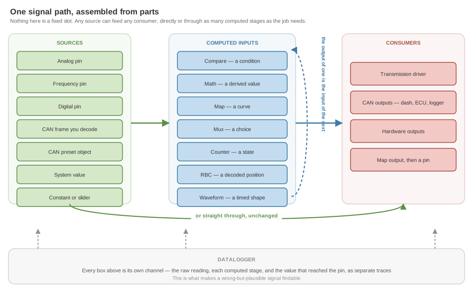
Nothing is a slot
A driver's mandatory brake element is not a pin. It is a reference to a named channel, and that channel can be anything that produces a value:
- an analog, frequency or digital pin;
- a signal you decoded out of a raw CAN frame yourself;
- an object a preset decoded for you;
- an internal value — battery voltage, ignition, the 5 V rail;
- a constant, or a slider you drag from the datalogger;
- or the output of any computed input — a comparison, a division, a curve, a decoded Gray code, a counter, a timed waveform.
The driver cannot tell which. It reads a number from a name.
That sounds abstract until you meet the real constraint: the gateways require seven mandatory inputs, eight on PDK, and no supported ECU stream carries all of them — see signal requirements. On a fixed-slot controller that is a wall. Here it is a wiring decision. The brake signal can come from a pedal switch on a pin, from a brake-pressure sensor through a curve and a threshold, from a frame you sniffed off the ABS module, or from a button on a CAN keypad — and every one of those is the same amount of work.
Computed inputs are inputs
This is the structural point the rest follows from. Compare, Math, Map, Mux, Counter, RBC and Waveform all consume inputs and produce inputs. Their output is not a special kind of value that only certain things can read — it is an ordinary channel, indistinguishable from a pin.
So they chain. The signal path is a graph you assemble, not a two-stage read-then-scale pipeline.
A brake signal built from a pressure sensor
Your ECU broadcasts no brake status and there is no spare switch. There is a brake-pressure sensor.
| Stage | Type | Produces |
|---|---|---|
| 1 | Analog Input, interpolation off | The pin, unscaled — a proportion of the 5 V range |
| 2 | Map Input | Bar, through the sensor's real curve |
| 3 | Compare Input, GreaterThan with a deviation |
A boolean with hysteresis, so a foot resting on the pedal does not chatter |
Stage 3 is what the driver's mandatory brake element points at. Three stages, three named channels, three separately visible traces.
A drive mode built from two paddles
| Stage | Type | Produces |
|---|---|---|
| 1 | Two Digital Inputs, filter on | One event per pull, not a level |
| 2 | Counter Input, min 0, max 2, rollover on | A mode number that wraps |
| 3 | Mux Input | The pressure target for the selected mode |
There is no "drive mode" feature in the firmware. It is assembled out of four generic parts, and changing it from three modes to five is one number.
A gear position from a Gray-coded selector
Digital pins, one per line, filters off → RBC Input → a gear number the strategy can act on. Again, no selector-specific code: the decoder is generic and the wiring decides what it means.
One value can go to several places
An input is not consumed by being read. The same channel that satisfies the driver's mandatory element can, at the same time, go out on a CAN output to a dash, feed a second Map that shapes it for a gauge, and drive a Compare that lights a warning.
The output side mirrors this. A Map Output sits between the strategy and the pin and linearises an actuator without the strategy knowing; and one command can drive several outputs at once, so two solenoids fed from the same source cannot drift out of step.
Every stage is a channel, so every stage is visible
Because each stage is a real input with a real name, the datalogger sees all of them. In the brake example you get the raw 0–1024, the pressure in bar, and the boolean as three independent traces.
That is not a convenience. A controller that scales inside a fixed block gives you the final number only, and when the final number is wrong you are guessing which half of the block is wrong. Here you can see the curve output is sane and the threshold is tripping late, and you know exactly which one to change.
It matters here more than most places, because of what the flexibility costs — see below.
Execution order, and the latency it decides
Every cycle the device runs, in this order:
- All computed inputs, in the order they were created.
- The input watchdog — the fault windows.
- The transmission drivers.
- The output drivers.
The loop runs at 1 kHz, so a cycle is a millisecond.
Two consequences worth knowing:
- A chain built in dependency order resolves inside one cycle. Pin → map → compare → driver all happen in the same millisecond. Depth costs nothing.
- A stage built out of order costs one cycle each. A computed input that runs before the input it reads sees the previous cycle's value. Nothing faults; the chain simply lags. Since a computed input can only reference an input that already exists when it is created, ordering is normally handled for you — but a hand-edited or imported configuration can get it wrong, and latency is the only symptom.
What it costs
The same property that makes this flexible is the reason nothing checks your work. There is no schema that says a brake element must be a boolean from a switch. Point it at a Math Input dividing two temperatures and the driver will take the number and set clutch pressure from it.
Every failure mode described across these pages is silent. A wrong signal does not announce itself; it looks exactly like a right one until the transmission behaves oddly under load, which is weeks later and somewhere else. That is the trade the architecture makes, stated plainly:
- The datalogger is not optional. Confirm every stage of every chain before anything depends on it. Read wrong but plausible once, properly.
- The freedom that lets you build a brake signal out of a pressure sensor lets you build a wrong one, with the same effort and no warning.
- Engine torque is the one that bites hardest, because nothing validates it in any calculation method and it sets clutch clamping pressure — the ten-minute check.
This is a construction kit, not a menu. That is the differentiator, and the discipline is the price of it.
Boundaries
Honest limits of the model, so you plan around them rather than discover them:
- Integer arithmetic throughout, on a 1024 full scale. Work in tenths or hundredths where you need a decimal — the 1024 convention. Sensor voltages are the exception: you enter those in volts and the app converts.
- No persistence. A Counter restarts from its start value on every power-up. Nothing in the signal path survives a power cycle.
- A few configuration fields do nothing, and they are listed rather than hidden: configuration fields that do nothing.
- Some limits are per-device, not per-configuration — IOcan has no analog voltage output and no tacho output at all, and the standalone controller can have only one tacho output. See which device has which IO.
Related
- Configuration concepts — the block-level picture this page details
- Configuring inputs · Configuring outputs
- Common IO settings — the conventions every stage shares
- Signal requirements — what each driver needs
- Working with the CAN bus