Getting Started with IOcan
This guide is intended for users who install, wire, and configure the IOcan device. It focuses on safe initial setup, first power-up, and basic validation of communication with the ECU and transmission.
It does not cover mechanical installation, vehicle-specific wiring, or detailed configuration logic.
Before you start: confirm your ECU actually provides the signals the transmission needs — Aftermarket ECU integration — and read Stated limitations so you know what this device does not do. If you are still choosing between a gateway and a standalone controller, start at Which device do I need?.
Quick Start Checklist
Typical first setup procedure:
- Connect IOcan to a PC via USB.
- Flash firmware and load a base configuration — see Build your first configuration.
- Wire BAT+, GND, KL15, CAN-H, and CAN-L — see the pinout.
- Verify IOcan communication in the configuration tool.
- Connect the transmission CAN and power lines — wiring concepts.
- Apply vehicle or bench power.
- Confirm that transmission parameters appear in the datalogger.
1. Intended Audience and Assumptions
This guide assumes the following:
- The user has practical knowledge of CAN bus, including:
- twisted-pair wiring
- termination rules
- basic network topology
- For vehicle installations:
- the mechanical installation is complete
- the engine can start and idle with a stable RPM
- For bench testing:
- a stable power supply is available
- the supply can provide at least 12 V and 5 A to power transmission electronics
This guide focuses only on electrical integration and logical setup of IOcan.
2. Important Notices and Disclaimers
IOcan is intended for off-road use only.
IOcan will execute exactly what the configuration requests. Incorrect configuration may result in unexpected or unsafe behavior. The user is fully responsible for ensuring that the configuration is correct, validated, and tested safely.
Each installation is different. There is no universal configuration that is safe for all vehicles or transmissions.
The user is responsible for safety during testing.
Bench vs Vehicle Use
- Bench mode:
- CAN communication testing
- transmission diagnostics readout and erase
- flashing transmission software
- flashing IOcan firmware
- modifying IOcan configuration (even without a transmission connected)
- Vehicle mode:
- ECU integration
- live engine interaction
- drivetrain testing
Power and Wiring Safety
- In a vehicle installation, a 30 A fused BAT+ supply is recommended.
- On a bench, a current-limited power supply is strongly recommended.
- The transmission is a critical powertrain component.
- All vehicle wiring must be done to a high automotive standard.
- Temporary connectors, solder-less blocks, or WAGO-style connectors are not acceptable in a vehicle.
- Proper crimping is required. Soldering is strongly discouraged as it leaves the flux residues in the wires which causes the wires to corrode and stiffen.
3. Minimal Required Interface to the Vehicle or ECU
Power Domains
IOcan uses separate power domains for configuration and operational power.
USB Power
- powers the internal controller
- used for configuration and firmware updates
- transmission power output remains disabled
KL30/BAT+ Supply
- powers IOcan and the transmission power stage
- required for normal operation
- connected directly to the battery through a fuse — IOcan manages its own sleep and draws under 0.5 mA with the ignition off
This is an IOcan-specific rule. The standalone transmission controller has no low-power sleep mode and must not be wired to permanent battery; its KL30 goes through a time-delay-off relay instead. If you are wiring that device rather than this one, read Adaptation data lost when the supply drops with the ignition before designing the harness.
KL15/Wakeup Signal
- enables active operation
- activates CAN communication and transmission wake-up logic
The minimal interface required for IOcan to operate consists of five connections:
- KL30 / BAT+ (constant battery supply)
- KL15 / IGN / Wake-up
- KL31 / GND / Chassis ground
- CAN High
- CAN Low
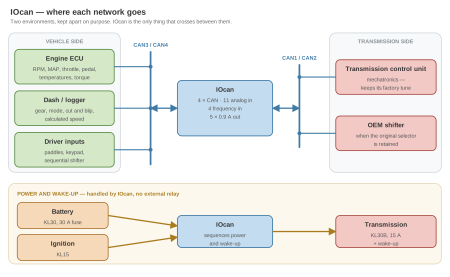
These connections allow IOcan to:
- wake up
- communicate on the CAN bus
- read required signals from the ECU or other modules
Supplying Missing Signals
If required signals are not available on CAN, they can be supplied using IOcan inputs:
- Analog inputs
- 0–12 V or 0–5 V depending on input — see the technical specifications
- can be mapped to CAN signals through configuration
- can be processed as digital signals
- resistor divider mode allows multiple buttons on a single analog input
- Frequency inputs
- intended for speed-based signals:
- engine speed
- wheel speed
- similar pulse-based signals
- intended for speed-based signals:
This is how most builds cover the gaps in their ECU stream. The brake signal is the one nearly everybody has to supply this way — it is mandatory on both gateways and is carried by almost no aftermarket ECU stream. See Signal requirements.
4. First Power-Up Using USB (Safe Mode)
The safest first power-up is performed using USB only.
- Connect IOcan to a PC using a USB-C cable.
- IOcan can be powered directly from the USB port.
In this mode, the user can:
- flash IOcan firmware
- modify and save IOcan configuration
- prepare the device before connecting vehicle or bench power
Transmission power is not active in USB-only mode.
This is the recommended starting point for all installations.
5. First Power-Up with Vehicle or Bench Power
After USB verification, IOcan can be powered from the vehicle or bench supply.
- Connect BAT+, GND, and KL15.
- When KL15 is asserted:
- IOcan becomes active on the CAN bus
- CAN communication is enabled
- transmission power and wake-up outputs are available
At this stage, the user should verify:
- IOcan is detected by the configuration tool
- CAN communication is present
- input signals behave as expected
This step confirms that wiring and basic configuration are correct.
Expected Behavior after KL15 is asserted:
- IOcan becomes visible in the configuration tool
- CAN traffic is visible on the bus
- the transmission wake-up signal is active
- transmission parameters appear in the IOcan datalogger
If these conditions are not met, verify wiring and CAN configuration.
6. CAN Bus Wiring Guidelines
- CAN wires must be twisted.
- Stubs should be as short as possible.
- The CAN bus must be terminated with 120 Ω resistors at each end.
Termination Rules
- IOcan has switchable internal 120 Ω termination.
- If IOcan termination is enabled:
- IOcan must be installed at the end of the bus
- only one additional termination resistor is used on the opposite end
- If two devices have internal termination enabled they must be installed at opposite ends of the bus
USB-only CAN operation may work in limited cases, but most ECUs require proper power and ignition to operate correctly. For reliable operation, all ECUs and modules should be fully powered.
Bench setups allow more flexibility, but vehicle wiring must be done with great care.
If the bus does not come up, work through CAN Bus Diagnostics — it is organised by what test equipment you have. If you are tapping the vehicle bus at the diagnostic socket, the OBD-II pinout has the four pins that matter.
7. Transmission Connection and First Startup
Transmission wiring depends on the specific transmission being used. Detailed wiring information is provided on transmission-specific pages: ZF 8HP · Porsche PDK · BMW DKG. The principles common to all of them — which side of the device each bus belongs on, and why — are on Wiring concepts.
The minimal transmission connections are:
- power
- wake-up
- ground
- CAN bus
IOcan supplies both power and wake-up signals to the transmission. External relays are not required.
Base Configuration Requirement
Before the first startup:
- a base configuration must be flashed to IOcan
- this configuration defines:
- which CAN ports are used
- which transmission is expected
Working configurations for each platform are documented on the configuration pages: 8HP · PDK · DKG. If this is your first one, Build your first configuration walks through it step by step.
After first startup:
- transmission parameters should be visible in the datalogger
- no communication-related fault codes should be present — see how to read and clear faults
8. ECU Signal Integration and Validation
The user must either:
Mandatory inputs
The gateway drivers check their mandatory inputs when the configuration is applied, and will not run if one is unassigned. The 8HP gateway requires seven:
- engine RPM
- manifold pressure (MAP)
- throttle position
- pedal position
- oil temperature
- coolant temperature
- brake status
The PDK gateway requires those seven plus vehicle speed — eight in total. This is the single most common mistake when porting a configuration from an 8HP build to a PDK one.
Engine torque is not in the list because it is not an assignable input: it is either taken from the ECU stream or calculated by the device, and nothing validates it. Getting it wrong damages clutches without raising a fault, so budget time for checking your torque model.
Thirteen outputs are checked the same way, which surprises people who assume outputs are optional. The full picture — per driver, including what happens when a signal is present but wrong — is on Signal requirements.
No supported ECU stream carries all of them. Every build sources at least one signal from outside its ECU preset, usually the brake switch on a device input. Check yours before wiring: Aftermarket ECU integration.
If required signals are missing or invalid:
- IOcan will detect the condition
- a fault will be set accordingly —
0x0001for a missing input,0x0011for a missing output, both listed in Fault codes
Current draw check
With a full valve body installed and the engine off:
- observed current through IOcan should not exceed approximately 2 A
This serves as a basic sanity check. A supply that sags when the transmission wakes, or a draw well above this, points at wiring — see Transmission wakes then immediately sleeps.
9. Final Configuration and Next Steps
After basic communication and power-up are confirmed, the user must finalize the configuration:
- verify signal scaling and correctness — scaling and maps
- configure shifter logic — shifter integration
- confirm engine parameter ranges, and in particular check the torque model
- test behavior in controlled conditions
This completes the initial setup process and prepares the system for detailed configuration and testing.
Where to go next
Configuration
- Configuration concepts — inputs, outputs, drivers and how they connect
- Build your first configuration
- Common IO settings
Your transmission
Your engine
- Aftermarket ECU integration — what each supported ECU actually provides
- Engine torque estimation
- Executing cut and blip in your ECU — read the blip warnings before tuning one
When something is wrong
- Troubleshooting — organised by symptom
- Fault codes and fault diagnostics
- CAN bus diagnostics
- Stated limitations — what the device does not do
- Glossary