Device Pinout
| Pin Name | Pin | Pin | Pin Name | Pin Name | Pin | Pin | Pin Name |
|---|---|---|---|---|---|---|---|
| ANALOG OUT1 | A1 | A2 | ANALOG OUT2 | FREQUENCY IN1 | A3 | A4 | FREQUENCY IN2 |
| ANALOG OUT3 | B1 | B2 | ANALOG OUT4 | FREQUENCY IN3 | B3 | B4 | FREQUENCY IN4 |
| ANALOG IN1 | C1 | C2 | ANALOG IN2 | ANALOG IN3 | C3 | C4 | ANALOG IN4 |
| ANALOG IN5 | D1 | D2 | ANALOG IN6 | ANALOG IN7 | D3 | D4 | ANALOG IN8 |
| ANALOG IN9 | E1 | E2 | ANALOG IN10 | ANALOG IN11 | E3 | E4 | ANALOG IN12 |
| DIGITAL IN1 | F1 | F2 | DIGITAL IN2 | DIGITAL IN3 | F3 | F4 | DIGITAL IN4 |
| CAN1H | G1 | G2 | CAN1L | CAN2H | G3 | G4 | CAN2L |
| PWM OUT1 | H1 | H2 | PWM OUT2 | PWM OUT3 | H3 | H4 | PWM OUT4 |
| PWM OUT5 | J1 | J2 | PWM OUT6 | PWM OUT7 | J3 | J4 | PWM OUT8 |
| PWM OUT9 | K1 | K2 | PWM OUT10 | PWM OUT11 | K3 | K4 | PWM OUT12 |
| WAKEUP/KL15 | L1 | L2 | sGND | GND/KL31 | L3 | L4 | GND/KL31 |
| SENSOR_5V | M1 | M2 | SENSOR_12V | BAT+/KL30 | M3 | M4 | BAT+/KL30 |
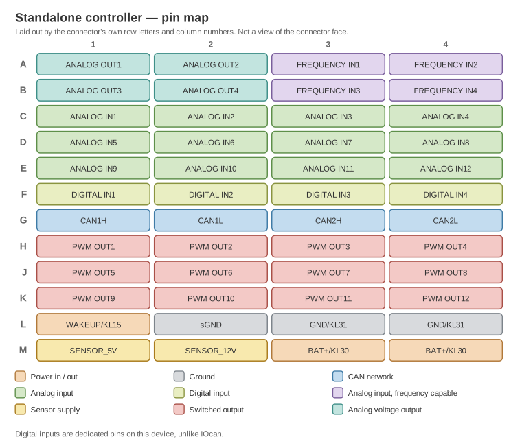
The same pins arranged by the connector's own row letters and column numbers, and coloured by function. It is not a view of the connector face.
Analog in
Inputs capable of measuring slow changing voltages up to 16V.
Frequency inputs
Input capable of registering periodic signals. Main use is reading signals like: Speed, PWM, injector pulse or similar.
Digital Inputs
Digital inputs are meant for slow, two state signals - they are GND active. Main use is user inputs: paddles, shift levers, buttons.
Analog output
It's a high impedance voltage output whose main purpose is to send voltage signals to other ECUs
PWM outputs
Those outputs are optimized for driving transmission solenoids. They are capable of outputting a PWM signal and they can drive load of up to 3A - relays, small valves. Depending on hardware version they are either low side or push pull (low and high side)
CANH and CANL
A pair of pins for connecting the device into a car canbus network.
SENSOR_5V
Main 5V supply for all sensors connected to the device. It's 200mA rated and it shouldn't be used to power any external digital electronic devices.
SENSOR_12V
Depending on the device version:
- A 12V 200mA source for external sensors
- An adjustable 200mA source for external sensors
sGND
Sensor ground connection. This pin is a central connection for all sensors that are connected to the device. Its main purpose is to provide a clean central point in star connection and to provide a ground reference for all connected senders.
GND/KL31
The chassis ground connection. This is a current-carrying connection and should be wired with care - proper crimp and 2x 1mm2 wires.
Wakeup/KL15
Battery+ through ignition signal. This input wakes up the device to active operation and signals the power off.
BAT+/KL30
Main power supply to the device. This is a current-carrying connection and should be wired with care - proper crimp and 2x 1mm2 wires. The supply should be a delay off supply - after the ignition turns off, this supply should be kept on for about 60 seconds for the device to save internal state to memory.
⚠️ Do not feed this from the same switched source as WAKEUP/KL15. With no delay, the supply disappears the moment the ignition does and the device loses power part-way through saving its state, which corrupts adaptation data.
Do not wire it to permanent battery either. The device has no low-power sleep mode — with KL30 present it keeps drawing 200–300 mA and will flatten the battery in hours.
Use a time-delay-off relay for KL30; the HELLA 5HE 996 152-131 is a known working part. Full detail: Adaptation data lost when the supply drops with the ignition.