VW DQ250 — Standalone Wiring
Running a DQ250 from the standalone controller means the OEM control unit comes out and the controller drives the mechatronics directly.
⚠️ This modification is not reversible. The OEM control unit is removed and its bond wires are destroyed in the process. A mechatronic unit prepared this way cannot be returned to standard, and it will not work in a standard car again. Be sure of the plan before starting.
Read DCT standalone drivers first — it covers the control strategy, its inputs and outputs, its parameters and its maps. This page is only the wiring.
Transmission-side preparation
- Cut the plastic cover on the mechatronic unit to reach the OEM control unit. There is no non-destructive way in.
- Remove the OEM control unit completely, including its bond wires.
- Drill a passage through the stock connector body and fit a 26-pin aftermarket connector into the sleeve. The stock connector shell is retained as the gearbox-side seal; only the contacts change.
Everything from here is soldered to the pads the OEM control unit used, which are labelled by connector group — TCU A through TCU H.
Transmission-side connectors
Each table is one connector group on the mechatronic unit, and gives the pin on the standalone controller that each terminal's wire ends at. L2 is the controller's sensor ground and M1 its sensor supply; both are shared across the groups and leave on one wire each.
What each terminal does on the transmission side is set by the driver and does not need to be known to build the harness — wire it as listed and confirm every channel in the datalogger afterwards.
Finding a terminal on the unit
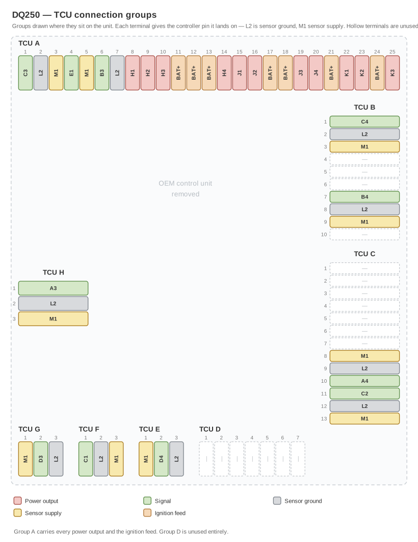
This is an overlay, not a key. Each group is drawn where it sits on the unit, around the footprint of the control unit you have just removed — group A along the top edge, B and C down the right, H on the left, and G, F, E and D across the bottom. Match the picture to the casting first, then count terminals within a group.
The groups are also distinguishable by terminal count alone — 25, 10, 13, 7 and four 3-way groups — so if the orientation is ambiguous, the counts settle it.
Two things worth noticing before you start soldering:
- Group A carries every power output, plus all seven ignition terminals. Most of the work is here.
- Group D is unused entirely. Nothing connects to any of its seven terminals.
The tables below are the same data in full, and are the ones to work from.
TCU A — 25 pins
The main group: every power output and the transmission's ignition feed.
| Pin | Connects to |
|---|---|
| 1 | C3 |
| 2 | L2 — sensor ground |
| 3 | M1 — sensor supply |
| 4 | E1 — plus a 2.2 kΩ resistor from this line to M1 |
| 5 | M1 — sensor supply |
| 6 | B3 |
| 7 | L2 — sensor ground |
| 8 | H1 |
| 9 | H2 |
| 10 | H3 |
| 11 | +12 V ignition |
| 12 | +12 V ignition |
| 13 | +12 V ignition |
| 14 | H4 |
| 15 | J1 |
| 16 | J2 |
| 17 | +12 V ignition |
| 18 | +12 V ignition |
| 19 | J3 |
| 20 | J4 |
| 21 | +12 V ignition |
| 22 | K1 |
| 23 | K2 |
| 24 | +12 V ignition |
| 25 | K3 |
TCU B — 10 pins
| Pin | Connects to |
|---|---|
| 1 | C4 |
| 2 | L2 — sensor ground |
| 3 | M1 — sensor supply |
| 4–6 | Not used |
| 7 | B4 |
| 8 | L2 — sensor ground |
| 9 | M1 — sensor supply |
| 10 | Not used |
TCU C — 13 pins
| Pin | Connects to |
|---|---|
| 1–7 | Not used |
| 8 | M1 — sensor supply |
| 9 | L2 — sensor ground |
| 10 | A4 |
| 11 | C2 |
| 12 | L2 — sensor ground |
| 13 | M1 — sensor supply |
TCU D — 7 pins
Not used. No connection to any of its pins.
TCU E, F, G, H — 3 pins each
Four separate three-pin groups.
| Group | Pin 1 | Pin 2 | Pin 3 |
|---|---|---|---|
| TCU E | M1 — sensor supply | D4 | L2 — sensor ground |
| TCU F | C1 | L2 — sensor ground | M1 — sensor supply |
| TCU G | M1 — sensor supply | D3 | L2 — sensor ground |
| TCU H | A3 | L2 — sensor ground | M1 — sensor supply |
The replacement harness
The 26-pin connector fitted into the stock sleeve carries everything out to the controller. Sensor ground and sensor supply are consolidated internally, so each leaves on a single wire rather than one per group.
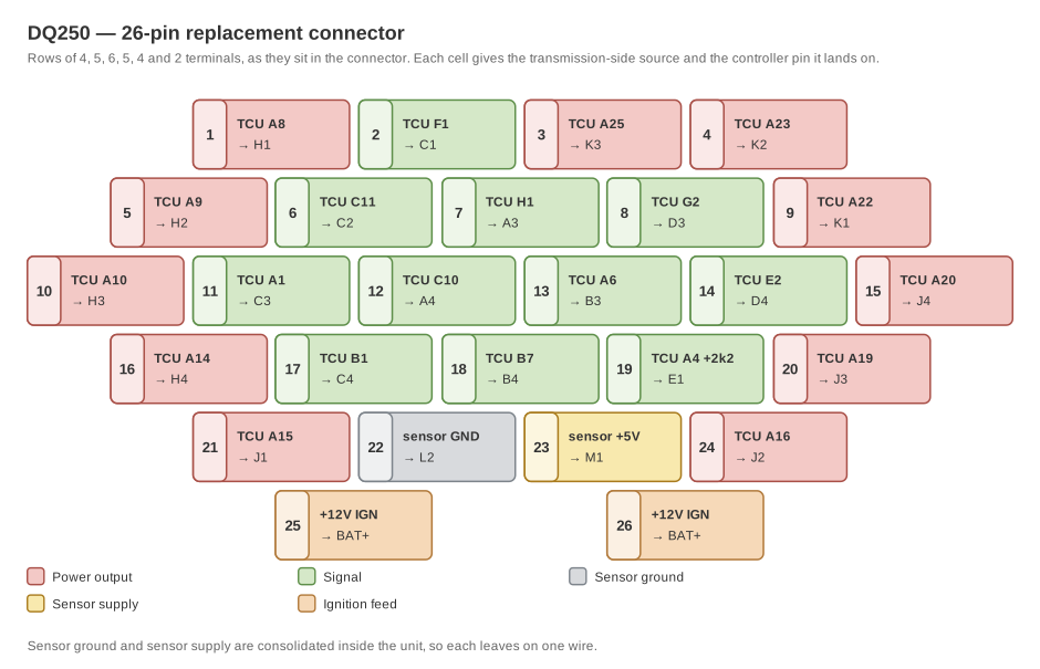
Terminals are shown in the connector's own rows — 4, 5, 6, 5, 4, 2 from the top. The final pair sits in the same two columns as pins 17 and 19. Which way round you see it depends on whether you are looking at the connector or the socket, so check a terminal you can identify before counting from an end.
| Pin | From | To controller pin |
|---|---|---|
| 1 | TCU A8 | H1 |
| 2 | TCU F1 | C1 |
| 3 | TCU A25 | K3 |
| 4 | TCU A23 | K2 |
| 5 | TCU A9 | H2 |
| 6 | TCU C11 | C2 |
| 7 | TCU H1 | A3 |
| 8 | TCU G2 | D3 |
| 9 | TCU A22 | K1 |
| 10 | TCU A10 | H3 |
| 11 | TCU A1 | C3 |
| 12 | TCU C10 | A4 |
| 13 | TCU A6 | B3 |
| 14 | TCU E2 | D4 |
| 15 | TCU A20 | J4 |
| 16 | TCU A14 | H4 |
| 17 | TCU B1 | C4 |
| 18 | TCU B7 | B4 |
| 19 | TCU A4 — plus a 2.2 kΩ resistor from this line to M1 | E1 |
| 20 | TCU A19 | J3 |
| 21 | TCU A15 | J1 |
| 22 | Sensor ground, all groups | L2 |
| 23 | Sensor supply, all groups | M1 |
| 24 | TCU A16 | J2 |
| 25 | +12 V ignition | BAT+ |
| 26 | +12 V ignition | BAT+ |
The DQ250 loom is not the dual-clutch loom
⚠️ Do not fit a DKG or DQ500 patch loom to a DQ250. It is the same 26-pin connector and it will mate perfectly, but ten of the twenty-six pins land on different controller pins. Ten channels would be wrong, and the connector gives you no warning.
The DKG and DQ500 builds deliberately share one external loom. The DQ250 has its own allocation, and that is deliberate too — it is not an oversight to be tidied up later, so do not "correct" a DQ250 loom towards the dual-clutch one.
What is common is the skeleton: the switched outputs H1–H4, J1–J4,
K1 and K2, the two battery-positive pins, sensor ground and sensor supply,
and the 2.2 kΩ pull-up on pin 19. Sixteen pins agree. The ten that differ are
the sensor and analog channels, plus DQ250's extra power output:
| Pin | DKG / DQ500 | DQ250 |
|---|---|---|
| 3 | C2 | K3 |
| 6 | C3 | C2 |
| 7 | C4 | A3 |
| 8 | D1 | D3 |
| 11 | D2 | C3 |
| 12 | A3 | A4 |
| 13 | A4 | B3 |
| 14 | D3 | D4 |
| 17 | D4 | C4 |
| 18 | B3 | B4 |
Label the loom. Two patch looms that mate with the same connector and carry different allocations are worth marking at the connector end, not just at the controller end.
Wire gauge
Inside the mechatronic unit, room is the constraint; outside it, current is.
| Run | Gauge |
|---|---|
| +12 V ignition, outside the unit | 1.5 mm² |
| +12 V ignition, split internally between the seven TCU A pins | 0.5 mm² |
| Power output wires | 0.5 mm² |
| Everything else | ≈ 0.25 mm² |
The single 1.5 mm² ignition feed splitting into seven 0.5 mm² tails inside the unit is deliberate: all seven pins are the same net, and the internal runs are short.
The 2.2 kΩ pull-up
TCU A pin 4 will not read correctly without it.
The wire from TCU A4 runs to controller pin E1, unbroken. The resistor is not in that wire. It is a second connection: fit a 2.2 kΩ resistor between that same line and the controller's sensor supply, M1.
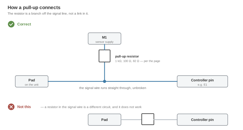
Put it at the controller end, where it stays reachable. It is the only component in the harness, it is easy to leave out, and it is hard to spot afterwards — the channel reads wrong rather than reading nothing.
Before first power-up
- Give BAT+/KL30 a time-delay-off supply. The controller writes its state after the ignition drops, and this driver learns adaptations that are lost if the supply goes at the same moment: advisory.
- Confirm every channel in the datalogger before letting the driver command anything. A channel that reads plausibly but wrong is the failure mode these pages keep warning about, and it is far cheaper to find now than on the road.
- Check the pull-up on TCU A4 while you can still reach it.
Related documentation
- Device pinout — the controller connector, and the supply requirements
- DCT standalone drivers — the control strategy this wiring serves
- DKG standalone wiring — the same job on a BMW dual-clutch unit, with the mechatronics pad maps
- Stated limitations