Wiring Concepts
This page explains the general wiring philosophy used when integrating IOcan into a vehicle or bench setup. The goal of IOcan is to act as an intelligent gateway between two different communication environments:
- the vehicle side, which contains the engine ECU, driver inputs, and other vehicle systems
- the transmission side, which contains the transmission control unit and transmission-specific components
IOcan connects these environments and translates signals between them. For detailed pin assignments see: CAN Gateway Pinout
System Architecture
In a typical installation, IOcan sits between the vehicle electronics and the transmission.
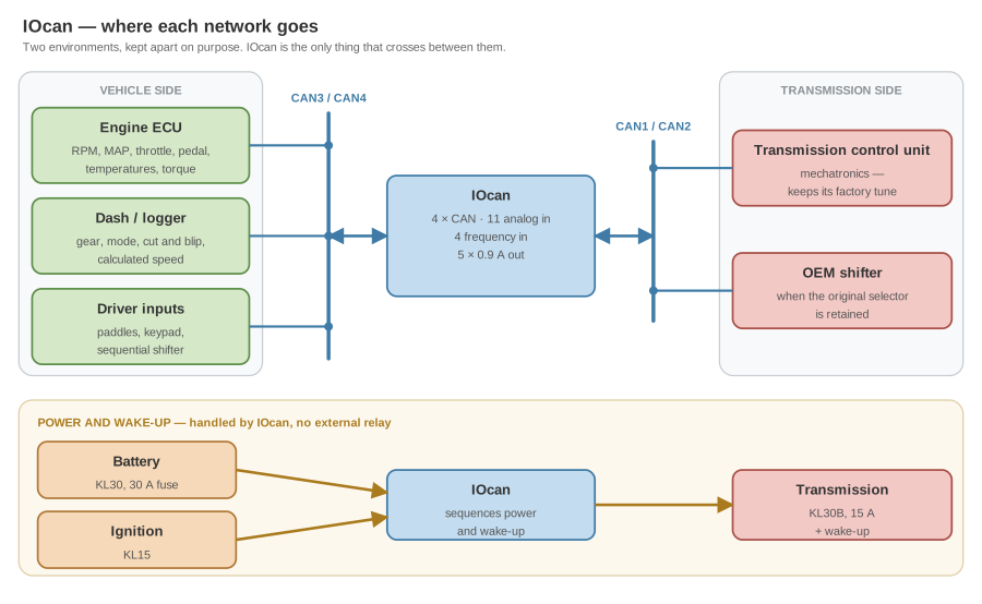
The device manages communication between these two environments and ensures that the transmission receives the signals it expects. It also supplies the transmission's power and wake-up itself, so no external relay is involved — that half is covered under Power Architecture.
CAN Network Separation
IOcan provides four independent CAN interfaces.
These are typically divided into two functional groups:
| Network | Typical Purpose |
|---|---|
| CAN1 / CAN2 | Transmission-side networks |
| CAN3 / CAN4 | Vehicle-side networks |
Vehicle Side
The vehicle wiring is usually connected to CAN3 or CAN4. Typical vehicle-side devices include:
- engine ECU
- body modules
- dashboard
- driver input devices
- auxiliary controllers
These networks contain signals originating from the vehicle environment.
Transmission Side
The transmission and related components are normally connected to CAN1 and CAN2. These networks are dedicated to communication with the transmission control unit and transmission-related devices. Separating the vehicle and transmission networks allows IOcan to:
- translate signals between protocols
- filter or modify messages
- emulate missing vehicle modules
Driver Input Devices (Shifters)
Driver input devices can be connected on either side of the system depending on the type of shifter used. IOcan is capable of emulating transmission shifter communication, which allows non-standard input devices to be used.
Non-Standard Shifters
Examples include:
- paddle shifters
- sequential shifters
- CAN-based keypads (for example Blink Marine keypads)
- custom switch panels
These devices should normally be connected to the vehicle side of IOcan.
IOcan processes the driver input and generates the appropriate OEM shifter commands for the transmission. This allows almost any input method to control the transmission.
OEM Shifters
If the original shifter designed for the transmission is used, it should normally be connected to the transmission side CAN network. In this configuration the shifter communicates directly with the transmission control unit, while IOcan supplies the remaining vehicle signals required by the transmission. This approach preserves the original communication behavior between the shifter and transmission.
Power Architecture
IOcan manages the power sequencing of the transmission. The recommended power wiring is as follows.
IOcan Power
IOcan should be connected directly to battery power.
Connections:
| Signal | Purpose |
|---|---|
| KL30 | constant battery supply |
| KL31 | ground |
| KL15 | ignition / wake-up signal |
KL15 is used to activate IOcan and enable CAN communication.
This is specific to IOcan, and it is the opposite of what the standalone transmission controller wants. IOcan has a real standby state — it sequences its own power and drops under 0.5 mA with the ignition off — so a permanent battery feed through a fuse is correct and will not flatten a battery.
The standalone controller has no low-power sleep mode at all. With KL30 present it keeps drawing 200–300 mA, so it must not be wired this way. Its supply goes through a time-delay-off relay instead, held about 60 seconds after the ignition drops so it can finish saving its state.
Wiring either device the other one's way causes a real failure — a flat battery in one direction, lost adaptation data in the other. See Adaptation data lost when the supply drops with the ignition.
Transmission Power
The transmission should be powered through IOcan.
Connections:
| Signal | Source |
|---|---|
| Transmission power | KL30B OUT from IOcan |
| Transmission wake-up | Wakeup output from IOcan |
The integrated power switch inside IOcan controls the transmission power supply and ensures proper startup and shutdown behavior.
Shifter Wake-Up Power
The wake-up signal for the shifter should normally be separate from the transmission wake-up signal. Recommended configuration:
| IOcan output | Powers / wakes |
|---|---|
| Digital output | Shifter wake-up |
| Wake-up output | Transmission wake-up |
Using separate wake-up lines avoids unintended interactions between the shifter and the transmission. Sharing the same wake-up line can interfere with the integrated transmission bench flasher functionality. For this reason, a dedicated digital output from IOcan should be used to power or wake the shifter when required.
Summary
Typical wiring arrangement:
| Component | Connection |
|---|---|
| Vehicle CAN networks | CAN3 / CAN4 |
| Transmission CAN networks | CAN1 / CAN2 |
| IOcan power | KL30 and KL31 |
| IOcan wake-up | KL15 |
| Transmission power | KL30B from IOcan |
| Transmission wake-up | IOcan wake-up output |
| Non-OEM shifters | vehicle side |
| OEM transmission shifters | transmission side |
This architecture allows IOcan to isolate the transmission communication network from the vehicle network while translating signals between the two environments.