VW DQ500 gen 1 — Standalone Wiring
Running a DQ500 from the standalone controller means the OEM control unit comes out and the controller drives the mechatronics directly.
⚠️ This modification is not reversible. The stock cover's rivets are drilled out, the flat-flex welded connections are broken, and the control unit is removed. A mechatronic unit prepared this way cannot be returned to standard. Be sure of the plan before starting.
This page is for the first generation. The second generation has a different pad layout, a different supply arrangement and a sensor that is not fitted from the factory — see DQ500 gen 2 wiring. Identify which you have before cutting anything.
Read DCT standalone drivers first — it covers the control strategy, its inputs and outputs, its parameters and its maps. This page is only the wiring.
What you need
- Soldering station
- Dremel with an abrasive disc
- Torx drivers
- Side cutters
- 24 AWG silicone or PTFE wire — oil resistant, rated to 200 °C
This work needs soldering experience and a steady hand. The joints are in tight locations and there is no room to be casual about them.
Opening the unit
Degrease the whole assembly once it is off the valve body. Universal degreaser or brake cleaner both work, and it makes every following step easier.
- Remove the solenoid connector plate, then drill out the rivets holding the stock control unit cover.
- Remove the plastic covers from the flat-flex cables and break the welded connections.
- Remove the aluminium cover of the stock control unit. Take care — the flex cables and sensors underneath are easy to damage and not easy to replace.
Pad connections
Pads are in seven groups. A, B, C and D are three-way; E and F are four-way; G sits on its own small carrier. Each row gives the pin on the standalone controller that the wire ends at.
L2 is the controller's sensor ground and M1 its sensor supply. Both are common across every group, so they can be joined at whatever point suits the routing rather than run individually.
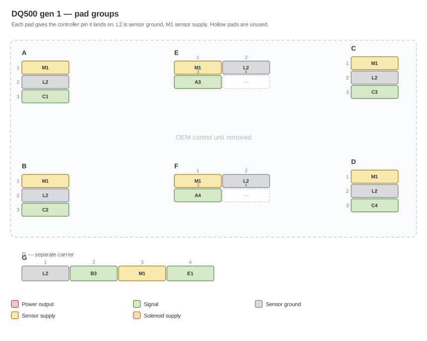
Groups are drawn where they sit on the unit. Match the picture to the casting before counting pads within a group.
| Group | Pad 1 | Pad 2 | Pad 3 | Pad 4 |
|---|---|---|---|---|
| A | M1 — sensor supply | L2 — sensor ground | C1 | — |
| B | M1 — sensor supply | L2 — sensor ground | C2 | — |
| C | M1 — sensor supply | L2 — sensor ground | C3 | — |
| D | M1 — sensor supply | L2 — sensor ground | C4 | — |
| E | M1 — sensor supply | L2 — sensor ground | A3 | Not used |
| F | M1 — sensor supply | L2 — sensor ground | A4 | Not used |
| G | L2 — sensor ground | B3 | M1 — sensor supply | E1 † |
† G4 needs a pull-up resistor. The wire from G4 runs to controller pin E1, unbroken — the resistor is not in that wire. It is a second connection: fit a 2.2 kΩ resistor between that same line and the sensor supply, M1.
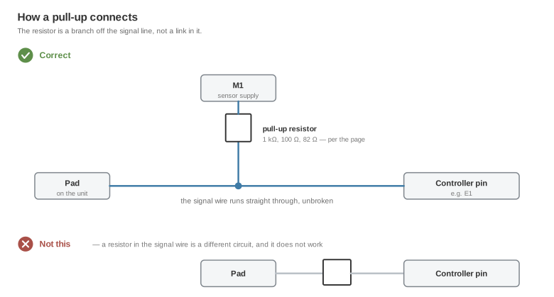
Put it at the controller end, where it stays reachable. It is the only component in the harness, and a channel that reads wrong rather than reading nothing is the symptom of leaving it out.
Note that group G does not follow the same order as A–F — its ground is pad 1 and its supply is pad 3. Read the row rather than assuming.
The sensor pads under the cover
A pair of sensors, A and B, sit under the stock control unit with their own solder pads marked VCC, SIG and GND. The stock controller bonded to the surrounding pads with fine aluminium wire.
Remove every bond wire with tweezers, holding each as close to its pad as possible so little or none of it is left behind. Then:
| Pad | Join | Connects to |
|---|---|---|
| 1 | A VCC and B VCC | M1 — sensor supply |
| 2 | A SIG | D3 |
| 3 | B SIG | D4 |
| 4 | A GND and B GND | L2 — sensor ground |
Follow the traces on the flat-flex cables to carry these out of the stock control unit's housing. Sensor ground and sensor supply are common with the pad groups above, so they can be joined wherever it suits the routing.
Solenoid connector
Fourteen positions. Three of them are the solenoid supply rail, not controller outputs.
| Position | Connects to |
|---|---|
| 1 | Solenoid supply |
| 2 | H1 |
| 3 | H2 |
| 4 | H3 |
| 5 | H4 |
| 6 | J1 |
| 7 | J2 |
| 8 | Solenoid supply |
| 9 | J3 |
| 10 | J4 |
| 11 | K1 |
| 12 | Solenoid supply |
| 13 | K2 |
| 14 | Not used |
The solenoid supply goes to switched ignition, and it must be live whenever the controller is powered. Size the circuit for a continuous 25 A — this is the one place on the page where the current is significant.
Controller-side connections
| Controller pin | Connect to |
|---|---|
| M3 and M4 | Battery positive — both pins |
| L1 | Switched ignition. Fuse it at 5 A |
| L3 and L4 | Engine or chassis ground — both pins, on a ground point you have confirmed |
| M2 | Available as a 12 V feed for a shifter, paddles or similar low-power auxiliaries |
⚠️ M3/M4 needs a time-delay-off supply, not a plain main relay. The controller writes its state after the ignition drops. A relay that opens with the ignition cuts the supply mid-write and corrupts the adaptations this driver learns. Hold it for about 60 seconds: advisory.
For the ECU side, the analog outputs on A1, A2, B1, B2 and CAN1 and CAN2 are available. Terminate the CAN bus with 120 Ω.
Sealing and routing
The steps that decide whether the job lasts:
- Check every joint before sealing, then protect the soldered points with silicone packing so nothing can short.
- Confirm there are no shorts between pads. Seal the pads, the sensors and the wires so they cannot move — movement is what eventually breaks a joint, and transmission fluid finds anything left open.
- Refit the rubber seal before the cover goes back on and the rivets are replaced. The cover has to seal. Fluid reaching the inside of the pan damages the sensors.
- Keep the solenoid loom away from the sensor loom. Do not braid them together — the switched wires are noisy and the sensor signals are the ones that suffer for it. Heat-shrink sleeving inside the case is worth the effort.
- The OEM round connector becomes a passage, nothing more. Drill it, lead the wires through, and seal it with a silicone packing such as Reinzosil.
If you fit a bulkhead connector instead of a plain feed-through, it is the same 26-pin round connector used on the DKG build — so the connector itself, its pin arrangement and its wire cross-sections are already documented on the DKG wiring cross table. One is worth fitting: it lets the internal loom be disconnected from the external patch loom without opening the unit again.
The pin allocation is published, and it is the same one the second generation uses: DQ500 26-pin connector cross table. Build to it rather than inventing your own — a patch loom made to that table fits either generation.
Before first power-up
- Give M3/M4 a time-delay-off supply — see the advisory above.
- Confirm every channel in the datalogger before letting the driver command anything. A channel that reads plausibly but wrong is the failure mode these pages keep warning about.
- Check the pull-up on G4 while you can still reach it.
Related documentation
- DQ500 gen 2 wiring — the other generation
- Device pinout — the controller connector and its supply requirements
- DCT standalone drivers
- DQ250 wiring — the same job on the smaller VAG unit
- Stated limitations