Adaptation data lost when the supply drops with the ignition
Published: 5 October 2024 · Status: Open — wiring change is the fix · Last reviewed: 2026-08-07
Affected
The standalone transmission controller, including every unit running legacy 1.x firmware, wired so that the ignition feeds both the wake-up input (KL15) and the main supply (KL30) with nothing holding the supply up afterwards.
The wiring is the trigger, not the firmware version. A controller whose KL30 is supplied through a time-delay-off relay does not have this problem on any version. A controller without one can have it on any version.
The controller has no low-power sleep mode, which is what rules out the obvious alternative of a permanent KL30 feed — see What to do.
IOcan is not affected, and the difference is architectural rather than a matter of degree. IOcan sequences its own power and has a real standby state, drawing under 0.5 mA with the ignition off, so a permanent battery connection through a fuse is correct for it — see Technical specifications.
What happens
Learned adaptation data is lost, or is subtly wrong, after the ignition is switched off. Shift quality degrades and the transmission behaves as though it has been reset.
It is usually intermittent. The save only fails when it is still in progress as the supply collapses, so it can take many ignition cycles before the damage is obvious — which is what makes it easy to attribute to the transmission instead.
Why
The controller writes its internal state to memory after the ignition signal goes away. That is by design: the ignition dropping is the signal that the state is final and can be committed.
Where the ignition also supplies KL30, removing the ignition removes the supply in the same instant. The processor loses power part-way through the write. An interrupted write does not simply leave the previous data in place — it can leave the stored block corrupt, which is worse than stale.
What to do
Supply KL30 through a time-delay-off relay driven by the ignition, holding the supply for about 60 seconds after the ignition goes off. That is enough for the write to complete.
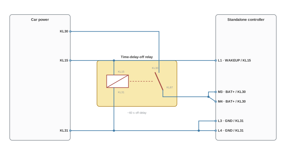
KL15 does two jobs. It goes straight to the controller's wake-up pin, and it drives the relay coil. The controller therefore sees the ignition drop immediately — which is what starts the save — while its supply stays up for the relay's off-delay.
| Controller pin | Function | Connect to |
|---|---|---|
| L1 | WAKEUP / KL15 | Ignition, directly |
| M3 and M4 | BAT+ / KL30 | Relay output (KL87) — both pins |
| L3 and L4 | GND / KL31 | Chassis ground — both pins |
| Relay terminal | Connect to |
|---|---|
| KL15 (coil / trigger) | Ignition |
| KL31 (coil return) | Chassis ground |
| KL30 (contact input) | Battery positive, fused |
| KL87 (delayed output) | Controller M3 and M4 |
Both supply pins and both ground pins are used. They are current-carrying connections and the pinout asks for proper crimps and 2 × 1 mm² per connection.
The HELLA 5HE 996 152-131 is a part I have used for this. Any relay with an equivalent off-delay works — the delay is the specification, not the part number.
Do not wire KL30 to permanent battery instead. It does give the controller the time it needs, and it will flatten the vehicle battery in a matter of hours.
The controller has no low-power sleep mode. There is no state it drops into when the ignition goes away — with KL30 present it keeps drawing 200–300 mA indefinitely. That is not a standby figure to be designed around; it is the running draw, and it is why a permanent feed is not an option here. The relay is what removes the supply once the save is done.
See Device pinout for the supply's conductor and crimp requirements — it is a current-carrying connection.
If a unit has already lost adaptation data, the adaptations need to be re-run once the wiring is corrected. A unit that will not adapt afterwards needs looking at — email contact@apex-control.com with the serial number, firmware version and transmission.
Status
Open. I have not shipped a firmware change for this.
The original notice said graceful shutdown procedures were being specified and would arrive in a later release. Searching the current firmware sources for a shutdown or power-loss save path finds nothing in the application code, so as of this review that work has not landed.
It would not retire the wiring guidance in any case. No firmware change can create hold-up time on a supply that has already been removed — the relay stays correct on every version.
Related
- Device pinout — supply and wake-up connections
- Troubleshooting
- Release history — legacy 1.x
- Fault codes