ZF 8HP — Standalone Wiring
This modification is irreversible. Grinding the TCM box open, pulling the bond wires and chiselling the stock module out permanently ends the mechatronics' ability to run under the factory TCU — and with it the option of driving the transmission through the IOcan gateway. If you want to keep the OEM TCU and the option of returning to stock, the IOcan route is the reversible alternative.
This page covers the ZF 8HP45, 8HP55, 8HP70, 8HP75, 8HP90 and 8HP90A. Running any of them on a standalone controller means modifying the mechatronics unit: the stock TCM comes out, and its solder pads are cross-wired so that every signal reaches the factory case connector. The case connector stays in service, so the finished transmission connects to the controller through a plain patch loom — no new bulkhead connector is needed.
The page is organised in two layers. Transmission-side modification covers all work on the transmission itself and is written without reference to any particular controller. Controller connections then assigns the case connector pins to controller pins.
What follows is one straightforward, low-risk way of carrying out the conversion. Any other method is just as valid, provided the finished point-to-point connections come out identical.
Transmission-side modification
Nothing in this section depends on which standalone controller will eventually run the transmission.
Required tools and materials
- Soldering station
- Dremel-type tool with grinding disc
- Torx set
- Side cutters
- 1 mm² (17 AWG) wire — silicone or PTFE insulated, oil resistant, 200 °C rated
Caution: the solder joints sit in very cramped locations. Take this job on only if you have soldering experience and a steady hand.
Disassembly
- Drain the transmission fluid by removing the screw in the oil pan.
- Unscrew the plastic oil pan.
- Disconnect the wiring connectors from the solenoids and the HIS.
- Pull out the metal plate on the side opposite the pump — it locks the round connector to the body.
- Unscrew the mechatronics unit.
Removing the stock TCM
Take the stock TCM off the valve body; behind it sits a metal box. Grind the cap off that box, keeping the grinder shallow at all times — the solder points just inside are easily destroyed by a disc that wanders too deep.
Pull the bond wires linking the stock module to the solder pads, then break the module itself out with a chisel.
Solder pad cross connections
The pads are arranged in three groups around the opened box: C18–C1 along the top, B1–B13 down the left side and A18–A1 along the bottom.
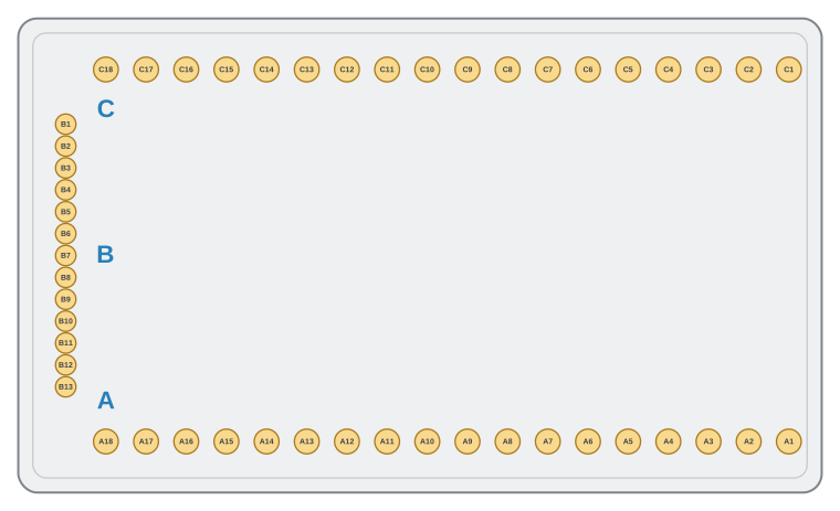
Pad field of the opened TCM box — C18–C1 along the top, B1–B13 down the left, A18–A1 along the bottom.
Solder link wires between the pads listed for your transmission variant, then bed the wires in silicone: it guards against short circuits and stops the wires from moving about inside the metal box.
8HP45 / 8HP70 / 8HP75 / 8HP90
| Pad | Connect to |
|---|---|
| A1 | C2 |
| A2 | C3 |
| A3 | C5 |
| A4 | C12 |
| A5 | C4 |
| A6 | C14 |
| A7 | B2 |
| A8 | B3 |
| A9 | B4 |
| A10 | B5 |
| A11 | B6 |
| A12 | C7 |
| A13 | C13 |
| A14 | B10, B11, B12, B13 |
| A15 | B10, B11, B12, B13 |
| A16 | B7 |
| A17 | B8 |
| A18 | B9 |
8HP55
| Pad | Connect to |
|---|---|
| A1 | C2 |
| A2 | C3 |
| A3 | C12 |
| A4 | B5 |
| A5 | C4 |
| A6 | C14 |
| A7 | B2 |
| A8 | B3 |
| A9 | B4 |
| A10 | B7 |
| A11 | B6 |
| A12 | C7 |
| A13 | C13 |
| A14 | B10, B11, B12, B13 |
| A15 | B10, B11, B12, B13 |
| A16 | C5 |
| A17 | B8 |
| A18 | B9 |
8HP90A
On the 8HP90A the round connector is cabled to the TCM plate, but the connections to its pins 2 and 11 are missing from the factory. Restore them with 1 mm² PTFE wire and clamps before soldering the pad links:
| TCM pad | Round connector pin |
|---|---|
| A1 | 11 |
| A13 | 2 |
| Pad | Connect to |
|---|---|
| A1 | C2 |
| A2 | C3 |
| A3 | B4 |
| A4 | B5 |
| A5 | C4 |
| A6 | B3 |
| A7 | B6 |
| A8 | C14 |
| A9 | B2 |
| A10 | C5 |
| A11 | C12 |
| A12 | C7 |
| A13 | C13 |
| A14 | B10, B11, B12, B14 |
| A15 | B10, B11, B12, B14 |
| A16 | B7 |
| A17 | B8 |
| A18 | B9 |
Case connector and patch loom
With the new wiring contained inside the unit, the factory case connector remains the transmission's interface to the outside world. Connect the transmission to the controller with a patch loom built to the case connector tables in Controller connections.
Controller connections
The pin assignments below apply to the standalone controller documented on the device pinout page. Any other device needs its own mapping tables in place of these — the transmission-side work above stays exactly the same.
⚠️ Two supply decisions belong in the harness design, not at commissioning.
- BAT+/KL30 needs a time-delay-off relay, holding the supply about 60 seconds after the ignition drops. The controller saves its state after KL15 goes away; cut the supply at the same moment and adaptation data is corrupted. The HELLA 5HE 996 152-131 is a known working part.
- Do not wire KL30 to permanent battery as the alternative. The controller has no low-power sleep mode — with KL30 present it keeps drawing 200–300 mA and will flatten the battery in hours.
Full detail: Adaptation data lost when the supply drops with the ignition.
Case connector
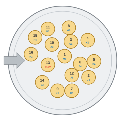
Face view of the 16-pin case connector with the controller pin assigned to each position.
| Case pin | Controller pin | Notes |
|---|---|---|
| 1 | SENSOR_5V (M1) | |
| 2 | PWM OUT7 (J3) | |
| 3 | ANALOG IN1 (C1) | add a 2.6 kΩ pull-up to SENSOR_5V (M1) |
| 4 | ANALOG IN2 (C2) | add a 500 Ω pull-up to SENSOR_5V (M1) |
| 5 | PWM OUT9 (K1) | |
| 6 | PWM OUT8 (J4) | |
| 7 | PWM OUT3 (H3) | |
| 8 | FREQUENCY IN2 (A4) | add a 100 Ω pull-down to sGND (L2) |
| 9 | PWM OUT5 (J1) | |
| 10 | FREQUENCY IN1 (A3) | add a 100 Ω pull-down to sGND (L2) |
| 11 | PWM OUT1 (H1) | |
| 12 | PWM OUT6 (J2) | |
| 13 | fused +12 V supply | |
| 14 | sGND (L2) | |
| 15 | PWM OUT4 (H4) | |
| 16 | PWM OUT2 (H2) |
All four resistors belong at the controller end of the loom: mount them close to the controller, positioned so they cannot suffer mechanical damage.
Power supply and grounds
- Battery +12 V, switched by the main relay, feeds BAT+/KL30 (M3, M4).
- Ignition-switched +12 V goes to WAKEUP/KL15 (L1). The controller has internal protection, but a 5 A fuse in this line is still advisable to guard the device against failure.
- Make the GND/KL31 ground connections (L3, L4) on the engine, or on the chassis provided the chosen chassis point is known to be sound.
ECU signals
The controller cannot work properly without signals from the engine ECU — they are what the transmission's configuration and mapping are built on. ANALOG OUT1–4 (A1, A2, B1, B2) and the CAN1 and CAN2 interfaces are available for communicating with the ECU.
Related documentation
- Device pinout — connector layout, inputs, outputs, and supplies
- ZF 8HP — Wiring (IOcan)